TRS Advanced WB Intel Issue 02.pdf - 第15页
Issue 2, Nov 14 TRS Advanced Maintenance 15 Mechanical System

TRS Advanced Maintenance
14
Issue 2, Nov 14
Drives and Sensors
Name Type Description
TRP Above Rails
Solid State Reed Switch 8SE81.
CAN Node 19 Dig In 4.
Indicates when the TRP has reached
the above rails position. Sensor fitted
to the rear of the TRA Cylinder body.
TRP Home
Solid State Reed Switch 8SE82.
CAN Node 19 Dig Out 5.
Indicates when the TRP has reached
the home position. Sensor fitted to
the front of the TRA Cylinder body.
Rail at Tooling
Forked Opto Switch 8SE78. CAN
Node 19 Dig In 0.
Indicates when the rail has lifted
prematurely indicating that there may
be an obstruction under the rail.
Rail Width Home
Forked Opto Switch 8SE79. CAN
Node 19 Dig In 1.
Indicates when the rail has reached
the home position.
Z-Lock Off
Solid State Reed Switch 8SE83.
CAN Node 19 Dig In 6.
Indicates when the z-lock is open.
Vacuum Pressure
Vacuum Leak Detector 8SE84.
CAN Node 19 analogue In 0.
Indicates the integrity of the vacuum
at: the vacuum seals, the tooling
towers and the substrate placement.
Tooling Present
Inductive Switch 8SE80. CAN
Node 19 Dig In 2.
Indicates that the active surround is
fitted. The functionality is disabled if
active surround is not detected.
Board Stop Up
Background Suppressed Opto
Switch 10SE26. NextMove
Interface Card X4
Indicates that the board stop is in the
up position.
Board Stop
Background Suppressed Opto
Switch 10SE25. NextMove
Interface Card X4
Indicates that the pcb handling
device has reached the stop sensor.
Board Stop (tooling
block)
Background Suppressed Opto
Switch. NextMove Interface Card
X4
Indicates that the strip has reached
the stop sensor.
Board Stop (Limit)
Up
Solid State Reed Switch. CAN
Node 19 Dig In.
Indicates that the stop cylinder has
reached the upper limit.
Board Stop (Limit)
Down
Solid State Reed Switch. CAN
Node 19 Dig In.
Indicates that the stop cylinder has
reached the lower limit.
TRP Present
Inductive Switch 8SE85 CAN
Node 19 Dig In 3.
Indicates that the TRP is fitted

Issue 2, Nov 14
TRS Advanced Maintenance
15
Mechanical System
TRS Advanced Maintenance
16
Issue 2, Nov 14
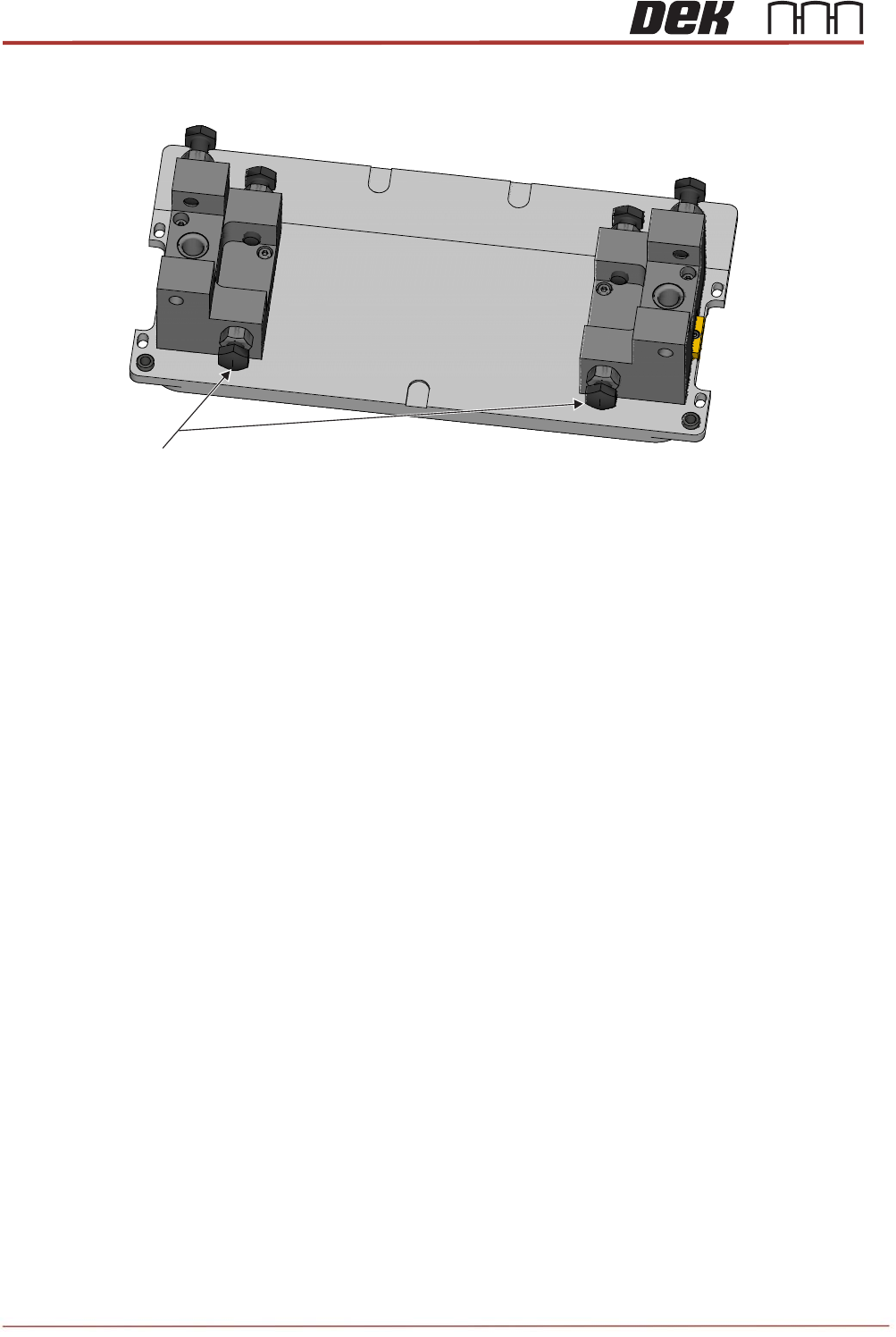
Objective 8: Rail Alignment Jig (RAJ)
Reference Block setting.
Rail width setting.
Rail parallelism setting.
Venturi vacuum seal test, (on the TRS base unit).
Board stop calibration (production).
Front Buttons
View on Rail Alignment Jig