TRS Advanced WB Intel Issue 02.pdf - 第22页
TRS Advanced Maintenance 22 Issue 2, Nov 14 Objective 10: Locate, remove a nd replace TRA Stripper Pins The stripper pins on the TRS assembly are there to aid separation of t he TRP plate from the Active Surround before …
Issue 2, Nov 14
TRS Advanced Maintenance
21
TRA Cylinder Tuning:
Reconnect the air to the machine, power up and enter diagnostics. Make fine adjustments to
the two sensor positions. Move the TRA as required to the trigger points.
• Home position.
• Over rails position (not pressured down). Ensure the sensor is positioned to trigger on
at this point and remain on while the TRA is pressured and the rising table translates
to vision height.
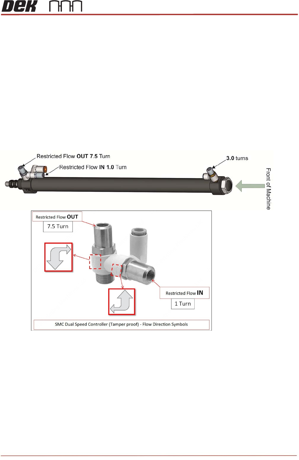
The flow control adjustment features are factory set to zero and require further adjustment.
Set the flow controllers using the special tool (212511). The required positions are as follows:
TRA (Left & Right) - Front (Out) = 3.0 turns from closed position.
TRA (Left & Right) - Rear(In) = 1.0 turn from closed position.
TRA (Left & Right) - Rear(Out) = 7.5 turns from closed position.
Apply a small dot of Varnistop Loctite 7400 to confirm setting has been done.
Cycle the TRP a few times to check consistent sensor operation and that Left Hand and
Right cylinders operate together (same speed), if not adjust Sensor position or flow
controllers.
NOTE
Cycle the TRA a few minutes to confirm there are no timing issues relating from speed,
sensor positioning or the function of the cylinders.
Observe the sensor states and confirm they are switching on at the over rails position and
home position.
TRS Advanced Maintenance
22
Issue 2, Nov 14
Objective 10: Locate, remove and replace TRA Stripper Pins
The stripper pins on the TRS assembly are there to aid separation of the TRP plate from the
Active Surround before returning to its home position.
Locate the Stripper Pins on the machine.
Remove and Replace both Stripper Pins:
Preparation
1. In Diagnostics, drive Rising Table to Transport Height.
2. Drive TRP over Rails Position.
3. Remove any previous stripper pin components and fixings.
4. Clean the two striker plates (behind rail cap) to remove any contact debris on both
side of the rail cap.
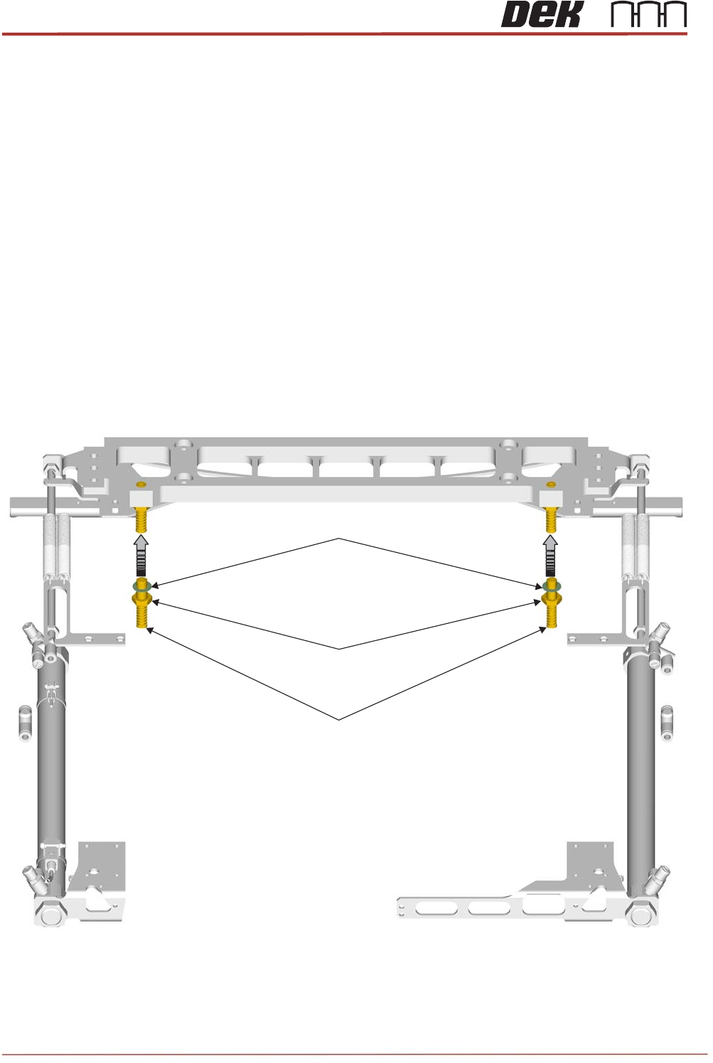
Replacement:
1. Assemble a half nut and crinkle washer onto each new pin assembly.
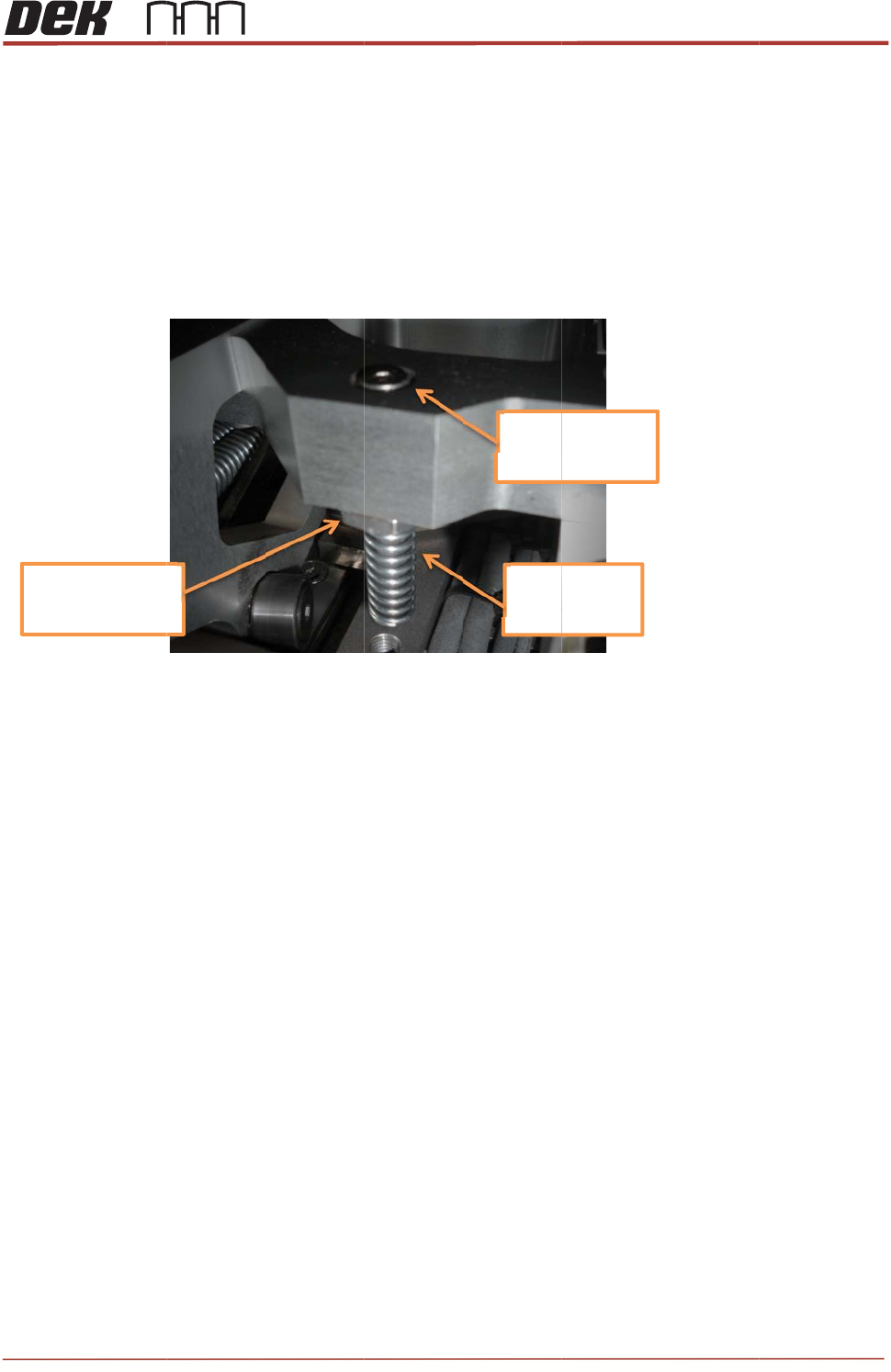
2. Insert the threaded part of each pin assembly upwards into the tapped holes of the bar
until the top surfaces are flush.
Stripper Pin Assembly
M10 Locknut
M10 Crinkle Washer
Issue 2,
3.
w
N
D
4.
T
s
5.
T
Note
s
Nu
t
to
1
Nov 14
Rotate th
e
w
ashers c
NOT
E
D
o not ap
p
T
ighten th
e
s
hould re
m
T
est the T
s
:
t
tightened
1
0Nm
e
pins app
r
ontact the
p
ly any Lo
c
e
nuts wit
h
m
ain close
RP move
m
oximately
bar.
c
tite.
h
a 17mm
to flush w
i
m
ent to en
s
¼ turn ba
c
spanner (
1
i
th the top
s
ure corre
c
c
k down a
n
1
0Nm). T
h
of the bar
.
c
t operati
o
+/‐0.
5
Toto
p
Spri
n
Dow
n
T
R
n
d wind th
e
e pins ma
y
.
No furthe
n of the S
t
5
mm
p
surface
n
gEnd
n
ward
R
S Advanc
e
e
nuts up
s
y
spin up
a
e
r adjustm
e
t
ripper Pin
s
e
d Maintena
2
3
s
o that the
a
little, but
e
nt is requ
i
s
.
nce
3
i
red.