TRS Advanced WB Intel Issue 02.pdf - 第23页
Issue 2, 3. w N D 4. T s 5. T Note s Nu t to 1 Nov 14 Rotate th e w ashers c NOT E D o not ap p T ighten th e s hould re m T est the T s : t tight ened 1 0Nm e pins app r ontact the p ly any Lo c e nuts…
TRS Advanced Maintenance
22
Issue 2, Nov 14
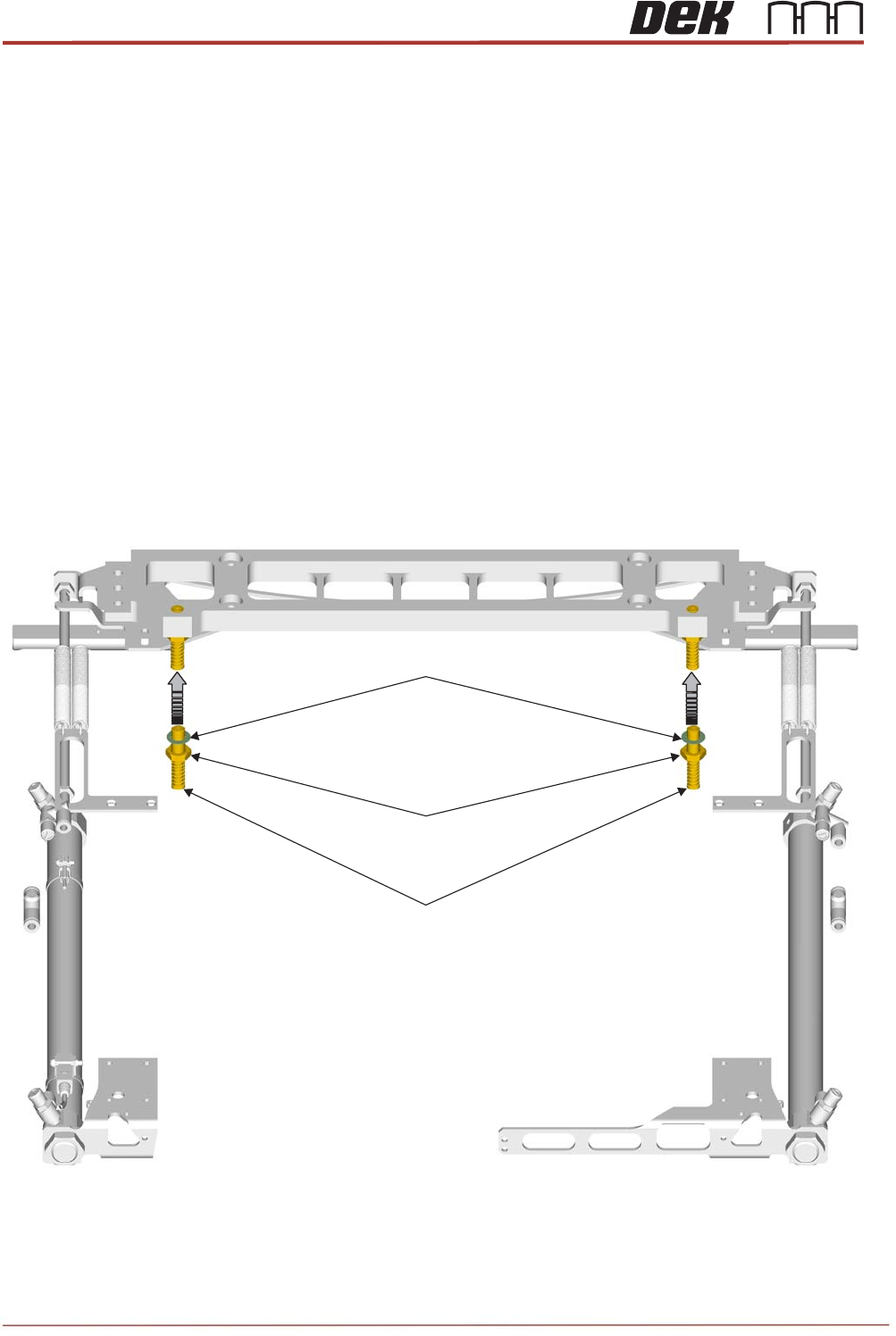
Objective 10: Locate, remove and replace TRA Stripper Pins
The stripper pins on the TRS assembly are there to aid separation of the TRP plate from the
Active Surround before returning to its home position.
Locate the Stripper Pins on the machine.
Remove and Replace both Stripper Pins:
Preparation
1. In Diagnostics, drive Rising Table to Transport Height.
2. Drive TRP over Rails Position.
3. Remove any previous stripper pin components and fixings.
4. Clean the two striker plates (behind rail cap) to remove any contact debris on both
side of the rail cap.
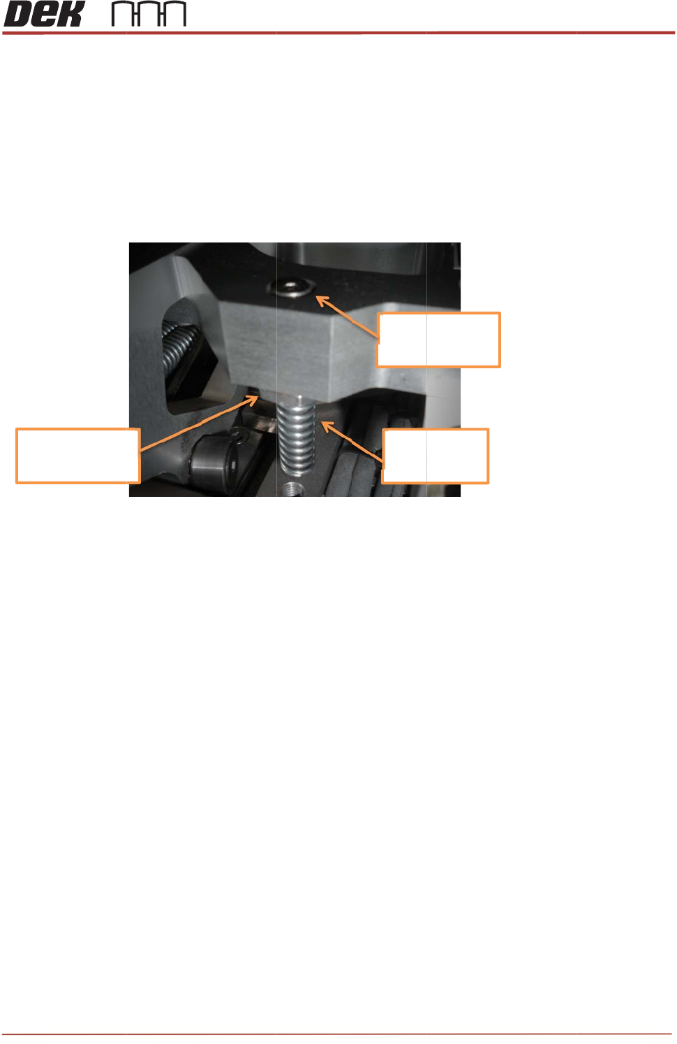
Replacement:
1. Assemble a half nut and crinkle washer onto each new pin assembly.
2. Insert the threaded part of each pin assembly upwards into the tapped holes of the bar
until the top surfaces are flush.
Stripper Pin Assembly
M10 Locknut
M10 Crinkle Washer
Issue 2,
3.
w
N
D
4.
T
s
5.
T
Note
s
Nu
t
to
1
Nov 14
Rotate th
e
w
ashers c
NOT
E
D
o not ap
p
T
ighten th
e
s
hould re
m
T
est the T
s
:
t
tightened
1
0Nm
e
pins app
r
ontact the
p
ly any Lo
c
e
nuts wit
h
m
ain close
RP move
m
oximately
bar.
c
tite.
h
a 17mm
to flush w
i
m
ent to en
s
¼ turn ba
c
spanner (
1
i
th the top
s
ure corre
c
c
k down a
n
1
0Nm). T
h
of the bar
.
c
t operati
o
+/‐0.
5
Toto
p
Spri
n
Dow
n
T
R
n
d wind th
e
e pins ma
y
.
No furthe
n of the S
t
5
mm
p
surface
n
gEnd
n
ward
R
S Advanc
e
e
nuts up
s
y
spin up
a
e
r adjustm
e
t
ripper Pin
s
e
d Maintena
2
3
s
o that the
a
little, but
e
nt is requ
i
s
.
nce
3
i
red.
TRS Advanced Maintenance
24
Issue 2, Nov 14
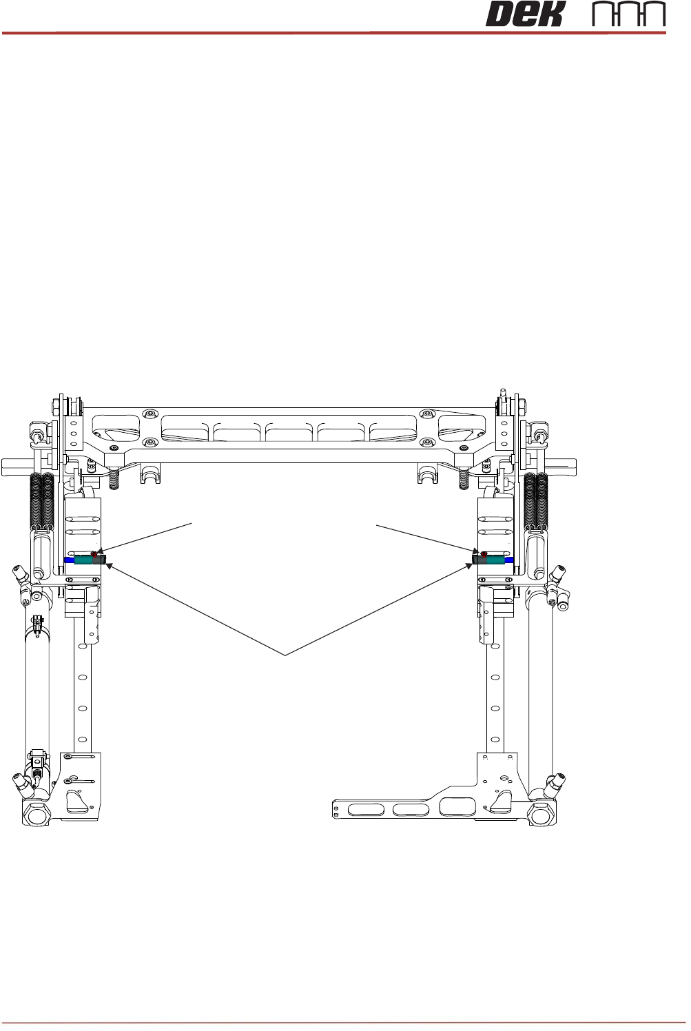
Objective 11: Replace TRA Interlock Pins
The Interlock pins can be found on the TRA slider body. Their purpose is to prevent the TRP
from lifting too high, before the plate is homed.(See Technical Reference Manual)
Locate the two Interlock pins on the machine. Discuss the operation of the Interlock pins with
your Instructor.
Remove and Replace the Interlock Pins.
Preparation:
1. Remove TRP and home the arm assembly.
2. Home rising table and power down printer.
3. Open cover and remove front access panel.
4. Locate the two interlock locations within the slider bodies.
5. Remove the two countersunk screws that are directly above the interlock caps.
6. Clean inside of the main bore and inside the brass bushing to remove any debris or
dust.
7. Discard all removed components.
Interlock Pin Assemblies
M3x5 Countersunk Head Screws