TRS Advanced WB Intel Issue 02.pdf - 第28页
TRS Advanced Maintenance 28 Issue 2, Nov 14 Setting the active surround plates with the special setting jig 1. Drive the rising table to transport height. 2. Loosely fit active surround lower plate on the rail cap. 3. At…
Issue 2, Nov 14
TRS Advanced Maintenance
27
Objective12: Remove and Replace Active Surround Plates
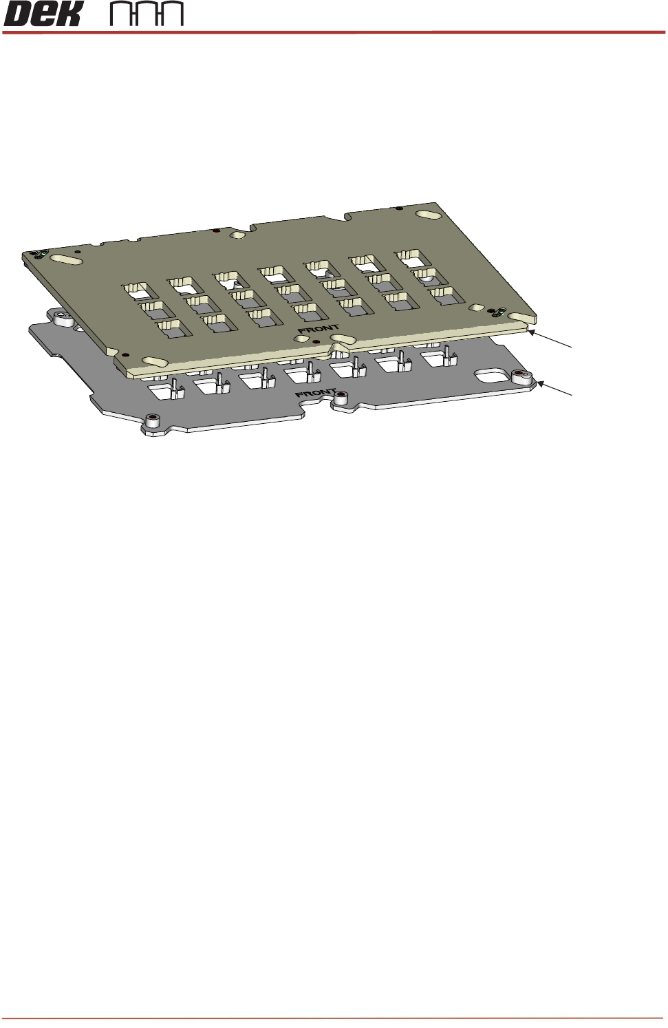
The Active Surround assembly is a set of two plates which are mounted to the bearings on
the Rail Cap. The Active Surround is operated by a pneumatic actuator to move the plates
45
o
to each other, this action will reference the substrates to one corner and will also hold the
substrates in position during printing.
Remove / Refit the Active Surround to the Rail Cap
Ensure the Pneumatic Actuator operates the Active Surround
Ensure the Active Surround holds substrates across all apertures.
Question:
What torque values are the Active Surround mounting screws tightened to..?__________
NOTES:
Upper Plate
Lower Plate
View on Active Surround Plate Assembly
TRS Advanced Maintenance
28
Issue 2, Nov 14
Setting the active surround plates with the special setting jig
1. Drive the rising table to transport height.
2. Loosely fit active surround lower plate on the rail cap.
3. Attach upper plate to the lower surround plate.
4. Once tighten all screws on active surround plates, undo the screws a quarter back to
allow plates move freely.
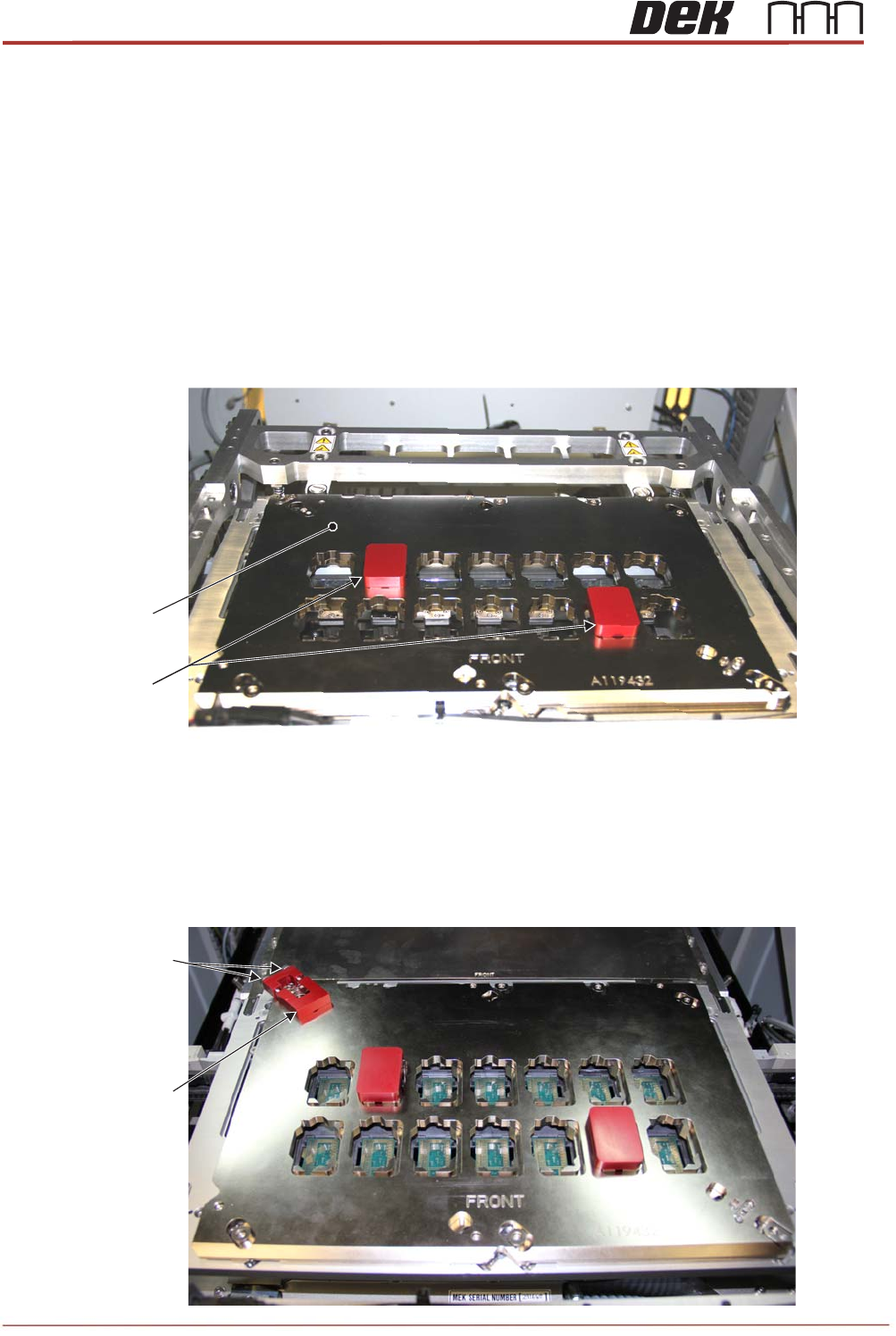
5. Place two setting blocks in to the surround plates as shown below.
6. Attach the setting plate to top left corner of the surround plates with pushing float
bearing screws towards to the corner.
7. Tighten 2 setting plate screws and torque up 1.8Nm to lock the setting plate into
position as shown below.
Setting Blocks
Active Surround
Plate
Setting Plate
Screws
Setting Plate
Issue 2, Nov 14
TRS Advanced Maintenance
29
8. Ensure 2 setting blocks move freely up and down but not to left or right.
9. Tighten all active surround screws and torque up to 1.8Nm.
NOTE
Do not drive the rising table to vision height when two setting blocks are fitted.
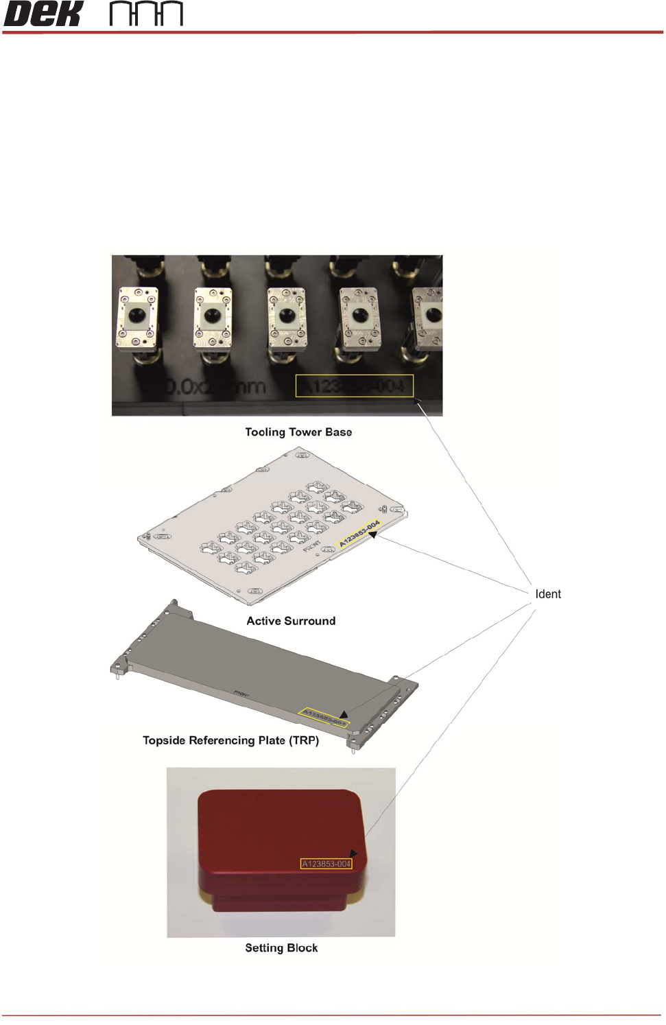
The system tooling has a unique identifier stamped into each unit. Operators and
maintainers should check the identification of tooling before use to ensure they all
match.