TRS Advanced WB Intel Issue 02.pdf - 第44页
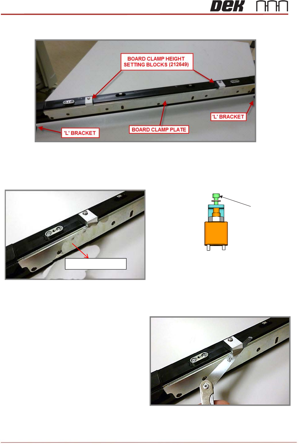
TRS Advanced Maintenance 44 Issue 2, Nov 14 6. Rotate both of the Setting Blocks forw ards and out over the Board Clamp plate. 7. Using an Allen key on M4x8 cap head screw (on the rail clamp adjustment block assembly), a…
Issue 2, Nov 14
TRS Advanced Maintenance
43
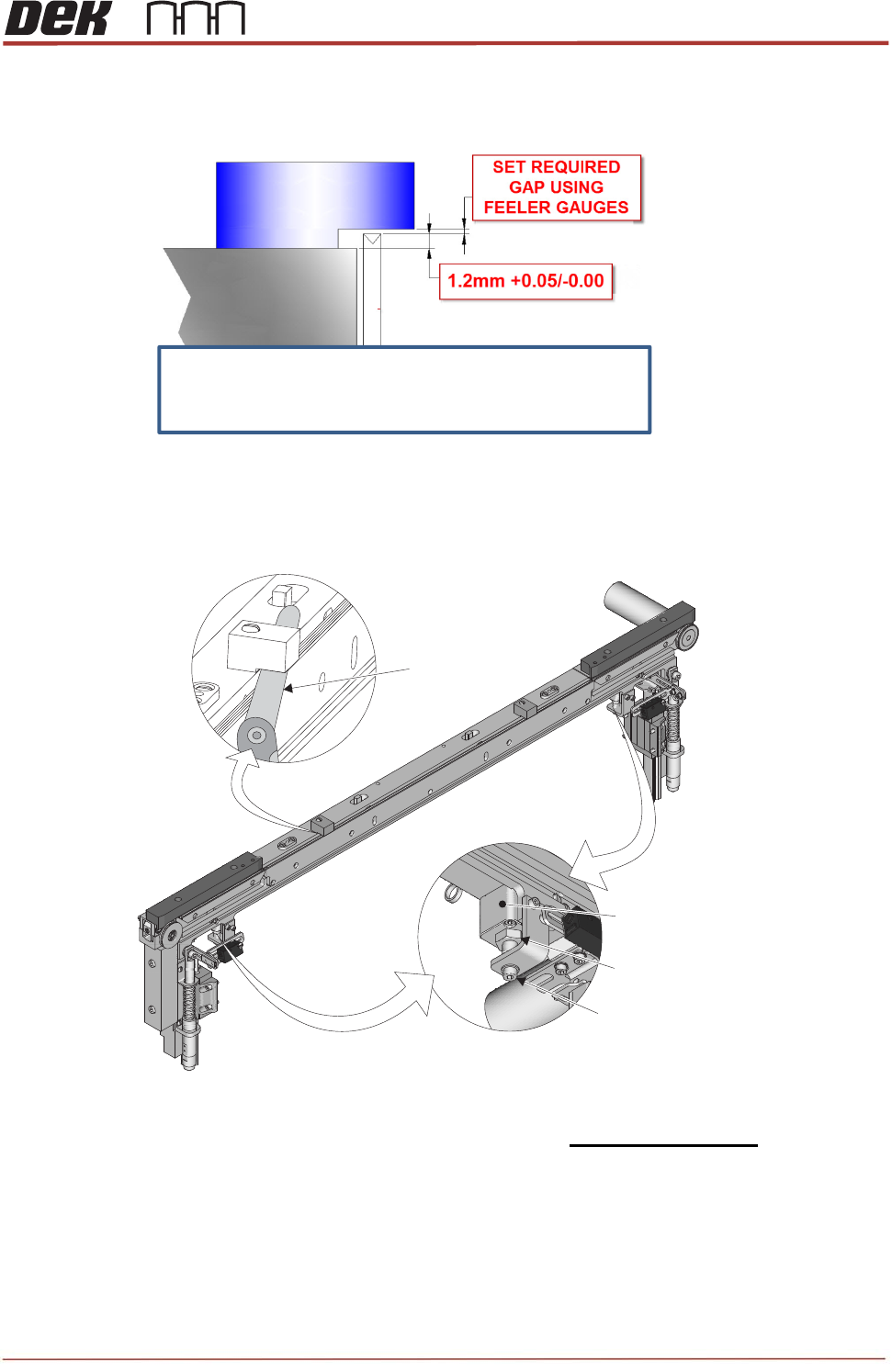
3. Subtract 1.2mm from the measured gap values above to determine the feeler gauge
thickness required in each location to achieve the correct gap and height setting.
NOTE
Using an Allen key on M4x8 cap head screw (on the rail clamp adjustment block
assembly), adjust the height of the Board Clamp Plates evenly using the calculated feeler
gauge thicknesses.
4. The top face of the Board Clamp Plate must be set @ 1.2mm +0.05/-0.00 higher than the
top face of the Centre Rail extrusion.
5. Use the measured gaps above to calculate the correct amount of feeler gauge required
and set the Board Clamp Height to within 0.05mm
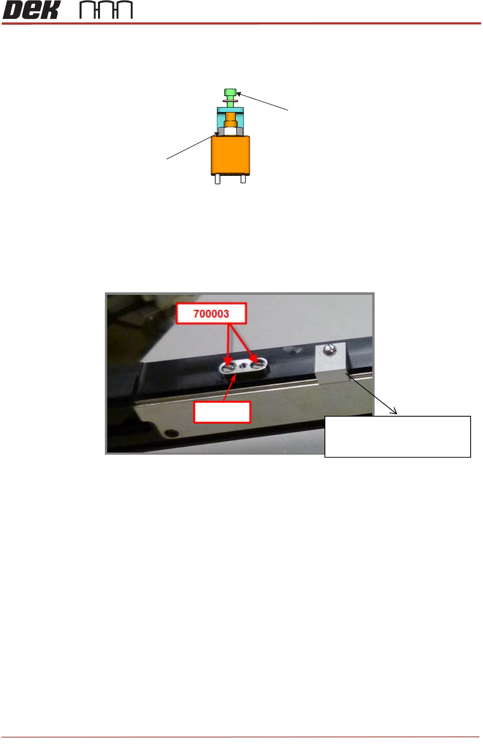
Adjustment Block
Lock Nut
Adjustment Screw
View on Rear of Front Central Rail Section
05
Feeler Gauge
Set the board clamp plate height using the
“Rail Cap Adjustment Block Assembly”
TRS Advanced Maintenance
44
Issue 2, Nov 14
6. Rotate both of the Setting Blocks forwards and out over the Board Clamp plate.
7. Using an Allen key on M4x8 cap head screw (on the rail clamp adjustment block
assembly), adjust the height of the Board Clamp Plates evenly using the calculated feeler
gauge thicknesses.
8. Continue fine adjustment until adding a
0.05 gauge makes the gap under each
Setting Block a very tight GO / borderline
NOGO.
View on Rail Clamp Adjustment Block Assembly
M4x8 Cap Head Screw
Board Clam
p
Plate
Issue 2, Nov 14
TRS Advanced Maintenance
45
9. Tighten the Lock Nuts on both and of the center section rail clamp adjustment block
assembly.
10. Re-check gaps & Varni-Stop if OK.
11. Repeat the height setting procedure for the rear center rail section.
12. Replace the 4x locating plates by using 8 off M3x8 pan head screws.
13. Apply pink Loctite 222 to each screws re-fit and after fully tighten them, back off each
screw by ½ turn.
14. Unscrew & remove the Board Clamp Height Setting Blocks. (212649 x2).
View on Rail Clamp Adjustment Block Assembly
M4x8 Cap Head Screw
M8x0.75 Nut Lock
158932
Board clamp height setting
blocks (212649x2)