TRS Advanced WB Intel Issue 02.pdf - 第68页
TRS Advanced Maintenance 68 Issue 2, Nov 14 89. Connect the loom marked 8PL224 to the break out socket plate on the rear of the MEK base. 90. Ensure that the cable is free to move up and down with the rail cap, any exces…
Issue 2, Nov 14
TRS Advanced Maintenance
67
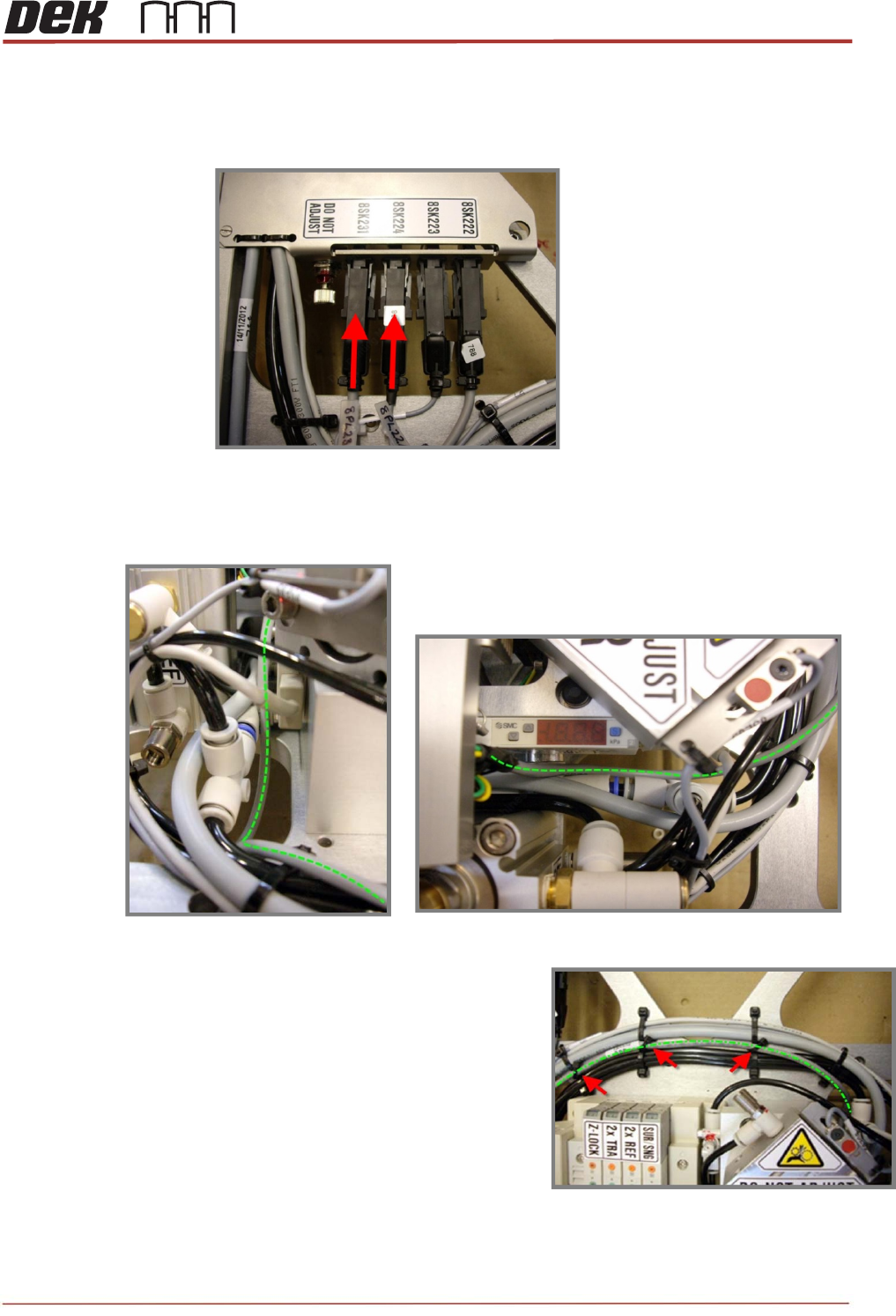
86. Connect the loom from the rear rail home sensor marked 8PL231 to the sockets on
the interface bracket as shown below.
87. The loom must sit between the pneumatic pipes and the sensor mount, ensure that
the cable is free to move up and down with the rail cap
88. Cable tie the loom in three positions along the
existing looms on the MEK base.
IMPORTANT: Keep the looms as low and flat to
the base as possible to avoid snagging when the
TRA cross-beam travels fully forward.
TRS Advanced Maintenance
68
Issue 2, Nov 14
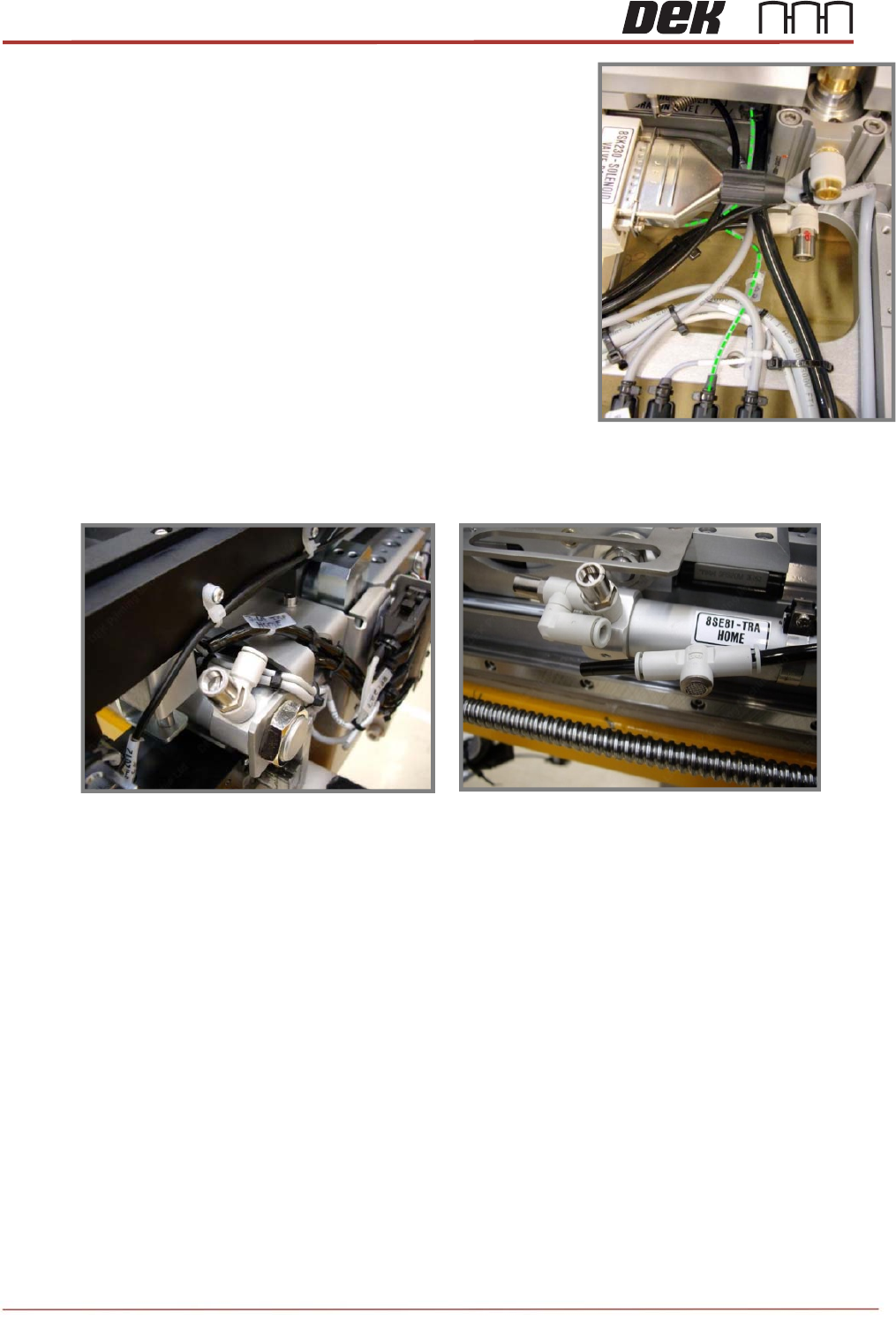
89. Connect the loom marked 8PL224 to the break out
socket plate on the rear of the MEK base.
90. Ensure that the cable is free to move up and down with
the rail cap, any excess can be allowed to loop into the
table casting round the pneumatic pipe.
91. Re-fit the pneumatic pipes to both ends of the LH TRA Sine Cylinder.
Issue 2, Nov 14
TRS Advanced Maintenance
69
Clatter Bar Height Setting;
Clatter bar height setting jig sets the height
from clatter bar to underneath the stencil
mount.
1. Check the height between clatter bar
and underneath the stencil mount.
2. Go to Diagnostics and home the rising
table.
3. Flag the active surround plate present
sensor on the rail cap (top LH) with a
metal feeler gauge.
4. Exit the rising table module*
5. Enter the rising table motor*
*Note
The last two actions are required to
reset the system flag for the active
surround present sensor.
6. Drive the rising table to vision height.
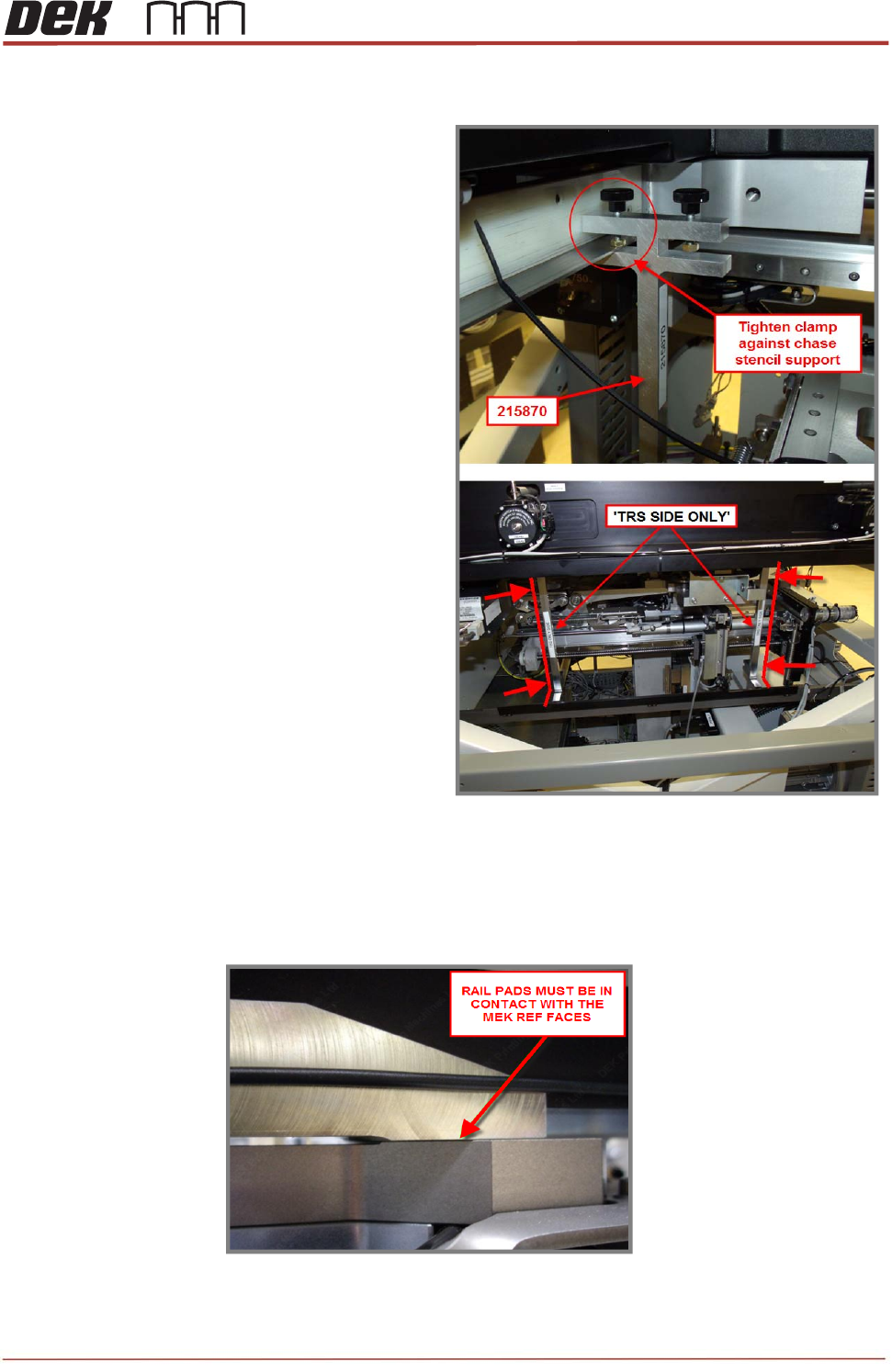
NOTE
Check that the front and rear rail pads are in contact with MEK base.