TRS Advanced WB Intel Issue 02.pdf - 第80页
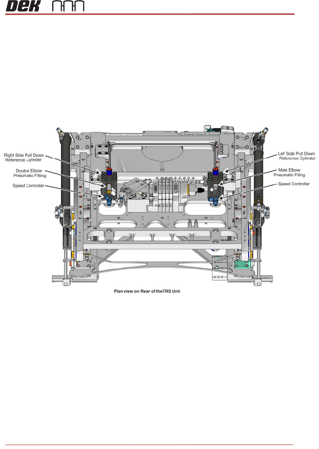
TRS Advanced Maintenance 80 Issue 2, Nov 14 6. Carefully, remove double elbow pneumatic fitting and male elbow pneumatic fitting from the right side pull down reference cylinder. NOTE 1. Keep pneumatic fittings safe for …
Issue 2, Nov 14
TRS Advanced Maintenance
79
Replacement Procedure
NOTE
Remove pull down reference cylinder one at a time.
1. Label three pneumatic pipes attach to right side pull down reference cylinder and note
the routing.
2. Disconnect three pneumatic pipes from the right side of pull down reference cylinder
assembly.
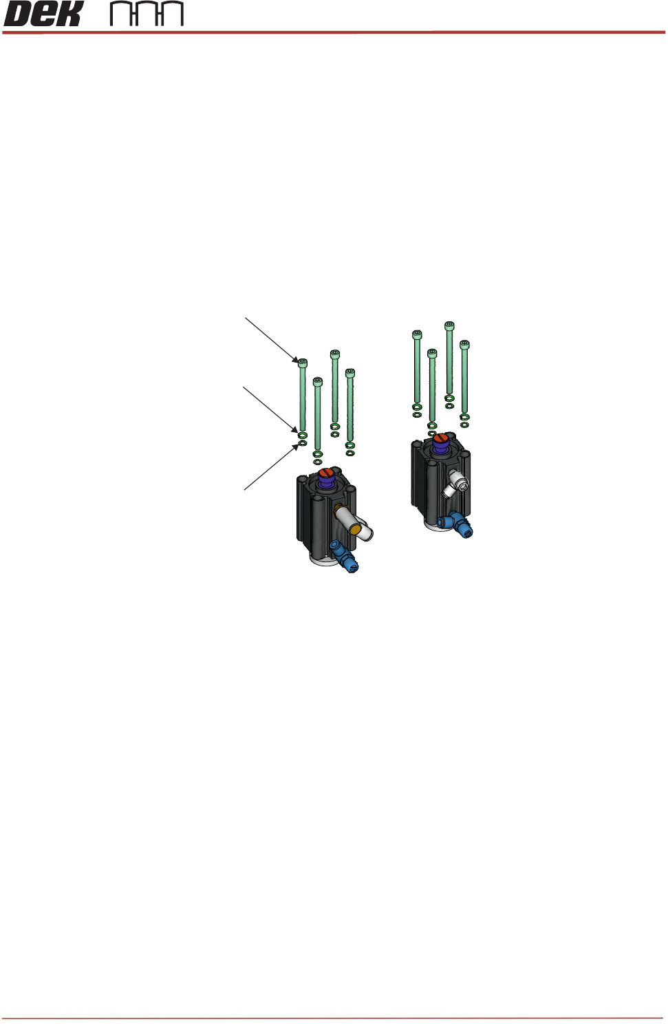
3. Undo 4 of M5x75 cap head screws and remove with M5 spring washers, M5 washers.
4. Carefully remove reference cylinder assembly from the TRS unit.
5. Repeat Steps 1 to 4 for left side pull down reference cylinder.
M5x75 Cap Head Screws
(8 Positions)
M5 Washer
(Reduced od)
(8 Positions)
M5 Spring Washer
(8 Positions)
Right and Left Side Pull Down Reference Cylinders
TRS Advanced Maintenance
80
Issue 2, Nov 14
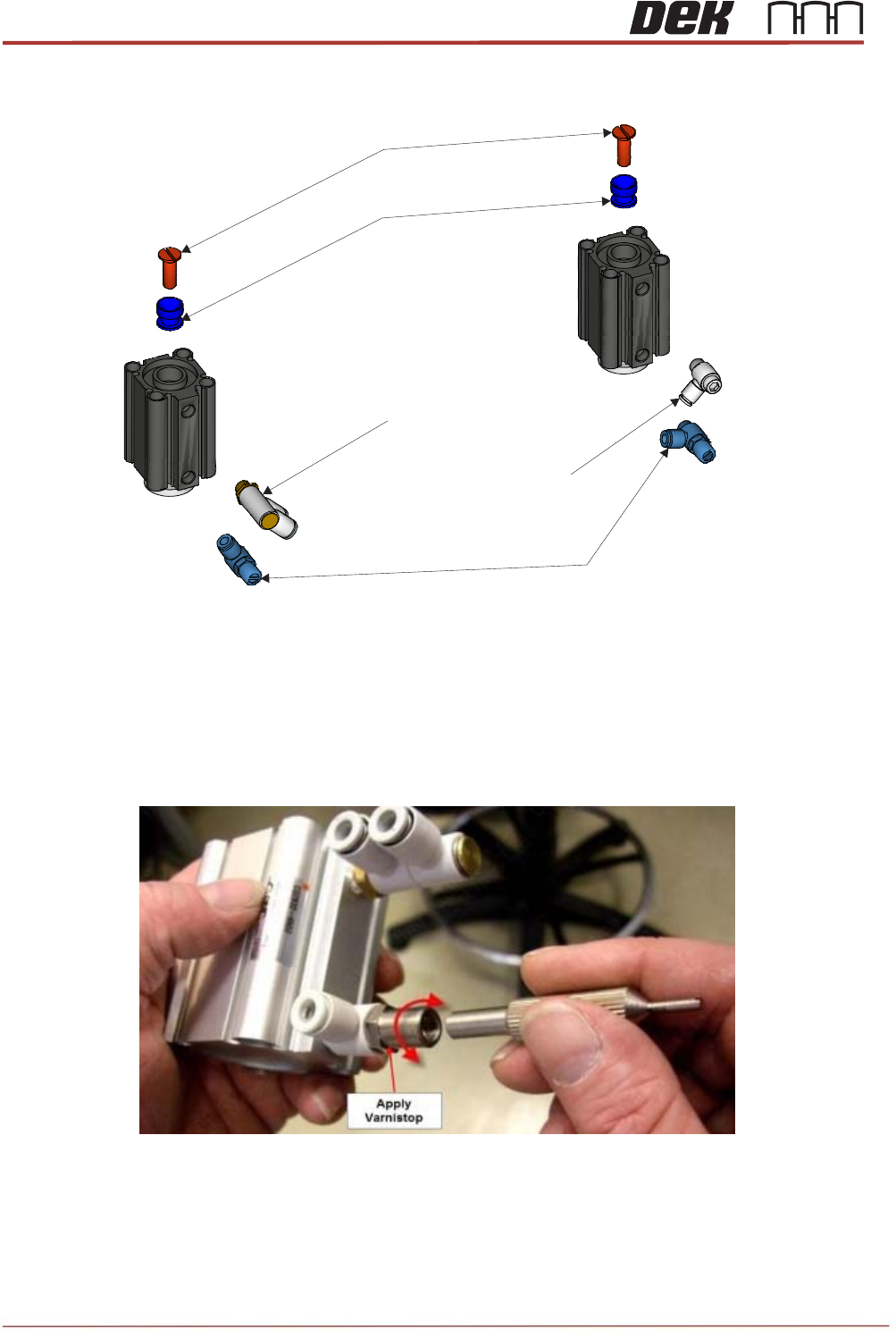
6. Carefully, remove double elbow pneumatic fitting and male elbow pneumatic fitting from
the right side pull down reference cylinder.
NOTE
1. Keep pneumatic fittings safe for future use.
2. If using a new flow controller set them fully in and back off 5 and a 1/4 turns by using
a special tool as shown below. Apply a small dot of Varnistop to the outside of the
adjuster to confirm setting has been done.
Locating Cap
M8x25 Slotted Countersunk Screw
Speed Controller
Double Elbow pneumatic
Fitting
Male Elbow Pneumatic
Fitting
Right Side Pull Down Reference
Cylinder Assembly
Left Side Pull Down Reference
Cylinder Assembly
Issue 2,
7. Ca
cyl
N
O
Ke
e
8.
A
tt
a
cyl
N
O
En
s
ol
d
9. Re
10. If fi
11. Tu
r
Nov 14
refully, re
m
inder by u
s
O
T
E
ep screw
a
a
ch pneu
m
inder.
O
T
E
s
ure fittin
g
d
cylinder
a
peat Step
s
tted, rem
o
r
n the po
w
m
ove M8x
2
s
ing 14m
m
a
nd cap s
a
m
atic fittin
g
g
s, screw
a
a
ssembly.
s
6 to 8 fo
r
o
ve the top
w
er ON.
2
5 slotted
c
m
spanner
a
fe for futu
r
g
s, M8x25
a
nd cap sit
r
the left si
d
reference
c
ountersu
n
and large
-
r
e use.
screw an
d
exactly th
e
d
e pull do
w
plate fro
m
n
k screw
a
-
flat blade
d
d
locating
c
e
same lo
c
w
n referen
m
the TRS
T
R
a
nd locatin
g
d
screwdri
v
c
ap to a n
e
c
ation and
c
e cylinde
r
arm asse
m
R
S Advanc
e
g
cap fro
m
v
er.
e
w right si
d
the same
r.
m
bly.
e
d Maintena
81
m
right side
d
e referen
c
position a
s
nce
c
e
s
the