00194888-01_DE_EN.pdf - 第75页
Installation Manual, Station Software Version 603.01 Issue 11/2006 3.2 SIPLACE X series and SIPLACE D3 hardware component s The following diagram shows the hardware components of the computer system for the X-series mach…

Installation Manual, Station Software Version 603.01 Issue 11/2006
12 of 62
Machine type
Subsystem BIOS / application Version File name
X2 X3 X4 D1 D2 D3 D4
BIOS
02.01
G0100201.HEX
X X X X X
Tape cutter
CAN, 500 KB
Application 1
03.02
G0110302.HEX
X X X X X
BIOS
01.00
G0200100.HEX
X X X X X
Tape cutter
CAN 1 MB
Application 1
01.00
G0210100.HEX
X X X X X
BIOS
01.00
G0300100.bhx
X X X
Tape cutter
X series
Application 1
01.01
G0310101.bhx
X X X
BIOS
03.06
T0400306.HEX
X X X
PCB conveyor
TSP201 ???
Application 1 06.0B T041060B.HEX
X X X
BIOS
02.06
T0500306.HEX
X X X
PCB conveyor
TSP301???
Application 1 06.0B T051060B.HEX
X X X
BIOS
03.06
T0600306.HEX
X X X X
PCB conveyor
HF???
Application 1 06.0B T061060B.HEX
X X X X
BIOS
03.24
E0100324.bhx
X X X X
Application 1
03.80
E0110380.bhx
X X X X
BIOS
03.24
E0200324.bhx
X X X
Main /
subdistributor
Application 1
04.04
E0210404.bhx
X X X
BIOS
03.CF
V05003CF.bhx
X X X X X
VISION modules
Application 1
03.02
V0510302.bhx
X X X X X
BIOS
02.00
M0200200.BHX
X X X
MTC 2
Application 1
02.05
M0210205.BHX
X X X
BIOS
01.00
M0400100.bhx
X
WPC 4
Application 1
01.01
M0410101.BHX
X
BIOS
02.04
L0200204.hex
X X X
Application 1
03.06
L0210306.hex
X X X
BIOS
02.04
L0300204.hex
X X X X
Digital pressure
regulation valve
Application 1
03.06
L0310306.hex
X X X X
BIOS
01.01
UA100101.HEX
X X X
X feeder
Application 1
01.36
UA110136.HEX
X X X
BIOS
01.00
UB200100.HEX
X X X
X feeder adapter
Application 1
01.00
UB210100.HEX
X X X
The hardware status of a subsystem is identified by the 3rd digit in the file name.
The example below shows the file name of the BIOS for the main axes of the X-Series:
File name Hardware status
A0
300200.bhx A 363
A0
400309.bhx A 364
Installation Manual, Station Software Version 603.01 Issue 11/2006
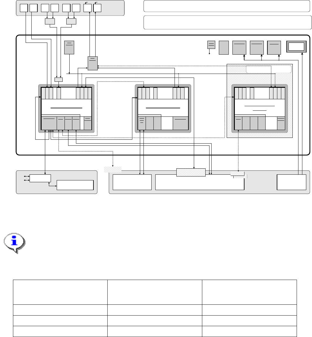
3.2 SIPLACE X series and SIPLACE D3 hardware components
The following diagram shows the hardware components of the computer system for the X-series machine
types and for the SIPLACE D3 machine type of the D series:
Camera system
for 1 - 2 placement areas with 2 - 4 placement heads with component vision
and PCB position recognition and optional coplanarity or 3D sensor
PS
Power supply
Computer unit
Fan unit
Manual
multiplexer
switching
only used
(video data
(stationary
images) via
hub)
Connect CD
drive to required
computer by
switching over
the USB cable
PS DC-DC
+-12V / 6A
KSP-SV501
PS DC-DC
+3.3V / 20A
KSP-NTS50-3
PS DC-DC
+5.0V / 60A
KSP-NTS50-5
+24 V
+52 V
Production line
LAN (hub)
1 2
CAN bus
Remote control
Machine
Y
cable
Touch -
screen 1
User
interface
Y
adapter,
keyboard
Y
adapter.
mouse
Video
Multi-
plexer
Touch -
screen 2
Keyboard
1
Keyboard
2
Mouse
1
Mouse
2
Monitor
1
Monitor
2
Structure of the computer unit and its interfaces
Line computer
SIPLACE Pro
Line computer and
external networks
LAN
+3.6V
Buffer
battery
to
CPUs
Slot
R
E
S
E
R
V
E
SIPLACE X2 / X3 / X4 and D3
Connection of options Software: 603 /
3-computer operation
CD
KSP-
MEM365
KSP-
VMP-HF
40 GB
HD FD
CPCI-MEM371
C P C I b u s
Machine controller
CAN
1 2
CPCI-
COM
168
R
E
S
E
R
V
E
R
E
S
E
R
V
E
L
A
N
C
O
M
A
C
O
M
B
V
G
A
U
S
B
1
U
S
B
2
K
E
Y
B
3D coplanarity option
40 GB
HD
CPU07x-
ZUBLPT
C P C I B u s
Vision computer
(optional)
L
A
N
C
O
M
A
C
O
M
B
V
G
A
U
S
B
1
U
S
B
2
K
E
Y
B
U
S
B
3
Splice
detectors
If the Vision computer option is used,
the coplanarity sensor option is not
used!
Only if the coplanarity
sensor option is used
40 GB
HD
CPCI-
MEM372
Station computer
C P C I - B u s
LAN HUB .
1 2 1 2 3 4
KSP-COM 294
L
A
N
C
O
M
A
C
O
M
B
V
G
A
U
S
B
1
U
S
B
2
K
E
Y
B
U
S
B
3
Hot-
link
PCI-A14
Hot-
link
PCI-A14
Serial
interface
PCI-...
+24 V+24 V
Coplanarity sensor with
USB interface
Option only in conjunction with S-Feeder (currently not planned) !
Special
interface
board
R
E
S
E
R
V
E
Camera
link
PCI-...
3D sensor
3D sensor
H
o
t
l
i
n
k
R
E
S
E
R
V
E
H
o
t
l
i
n
k
R
E
S
E
R
V
E
Fig. 3-1: Hardware components of the computer system for the SIPLACE X series and the SIPLACE D3 (schematic block diagram)
Note:
The hardware configuration of the station computer and the optional Vision computer can
only be combined with a particular hardware configuration for the machine controller. See
the following table for details.
Station computer
Machine controller Vision computer
(wit 3D coplanarity sensor
option)
SMP16-CPU086
SMP16-CPU076
SMP16-CPU086
SMP16-CPU086
SIMATIC Box PC 627
SIMATIC Box PC 627 SIMATIC Box PC 627
Table 3-1: Possible combinations of station computer and Vision computer with the machine controller
13 of 62

Installation Manual, Station Software Version 603.01 Issue 11/2006
14 of 62
3.2.1 Station computer
Name
SMP16-CPU086
CPU / clock frequency
P M / 1.6 GHz
RAM
768 MB
Hard disk
40 GB
External DVD drive
Yes
Serial interfaces
2
USB interfaces and
external USB hub
Yes
Network
1 x 10/100Base-T
2 x 10Base-T
6-port hub
Table 3-2: Station computer hardware (current configuration of SIPLACE X series and SIPLACE D3)
Name
SIMATIC Box PC 627
CPU / clock frequency
Pentium M / 2 GHz
RAM
1 GB
Hard disk
40 GB
External DVD drive
Yes
Serial interfaces
1
USB interfaces
and external USB hub
Yes
Network
2x 100 MBit
Table 3-3: Station computer hardware (future configuration of SIPLACE X series and SIPLACE D3)