00194888-01_DE_EN.pdf - 第78页
Installation Manual, Station Software Version 603.01 Issue 11/2006 16 of 62 3.2.3 Vision computer (optional) Name SIMATIC Box PC 627 CPU / clock frequency Pentium M / 2 GHz RAM 1 GB Hard disk 40 GB External DVD drive Yes…

Installation Manual, Station Software Version 603.01 Issue 11/2006
15 of 62
3.2.2 Machine controller
Name
SMP16-CPU076
CPU / clock frequency
Celeron / 650 MHz
RAM
256 MB
Hard disk
40 GB
External DVD drive
Yes
Floppy drive
3.5", 1.44 MB
USB interfaces
and external USB hub
Yes
Network
1 x 10/100Base-T
Table 3-4: Machine controller hardware (previous configuration of SIPLACE X series)
Name
SMP16-CPU086
CPU / clock frequency
Intel M / 1600 MHz
RAM
512 MB
Hard disk
40 GB
External DVD drive
Yes
USB interfaces
and external USB hub
Yes
Network
1 x 10/100Base-T
Table 3-5: Machine controller hardware (current configuration of SIPLACE X series and SIPLACE D3)
Name
SIMATIC Box PC 627
CPU / clock frequency
Pentium M / 2 GHz
RAM
1 GB
Hard disk
40 GB
External DVD drive
Yes
Serial interfaces
1
USB interfaces
and external USB hub
Yes
Network
2x 100 MBit
Table 3-6: Machine controller hardware (future configuration of SIPLACE X series and SIPLACE D3)

Installation Manual, Station Software Version 603.01 Issue 11/2006
16 of 62
3.2.3 Vision computer (optional)
Name
SIMATIC Box PC 627
CPU / clock frequency
Pentium M / 2 GHz
RAM
1 GB
Hard disk
40 GB
External DVD drive
Yes
Serial interfaces
1
USB interfaces
and external USB hub
Yes
Network
2x 100 MBit
Table 3-7: Vision computer hardware (optional for SIPLACE X2, X3 and D3 with 3D coplanarity sensor)
Installation Manual, Station Software Version 603.01 Issue 11/2006
3.3 SIPLACE D1, D2 and D4 hardware components
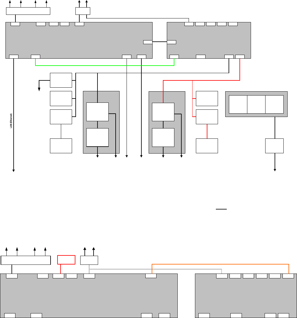
The following diagram shows the hardware components of the computer system for the D-series machine
types (except SIPLACE D3):
Structure of the computer unit with its interfaces
SIPLACE D1 / D2 / D4
LAN connection
Main switch
Line filter
Power connection
Power connection
Voltages
Protection
circuits
Fuses
Measuring
systems
Power supply
Station computer
SIMATIC Box PC 627
Pentium M 2 GHz, 1 GByte RAM, 40 GB HD,
2 x 100 MBit LAN, Graphics, 4 x USB, 1 x serial, 2 PCI slots
PCI 1: 1st hotlink
PCI 2: 2nd hotlink
LAN
VGA
Cameras
( 4 x component camera,
4 x PCB camera )
Measuring systems
Servo amplifiers
4 x X/Y
8 x head
Axis unit 2
USB1
VideoMux
Motors
Axes
( 3 x A364 )
12 axes
Servo amplifiers
4 x X/Y
8 x head
USB2 USB3 USB4
Hotlink Hotlink
Machine controller
SIMATIC Microbox 420
Pentium III, 933 MHz, 256 MByte RAM, 40 GB HD
2 x 100 MBit LAN, Graphics, 4 x USB, 1x serial, 3 x PC104
1st PC104: CAN bus ( 2x )
CAN 1
VGA
LAN 1
USB1
17 of 62
CAN 2
USB2
COM1
USB3 USB4
LAN 2
Motors
Processing area 1 Processing area 2
Monitor
1 2
Keyboard / Touchscreen
1 2
1 MBit/s
500 kBit/s
1 MBit/s
500 kBit/s
Axis unit 1
100 MBit/s
LAN
USB hub
COM1
Conveyor controller
PCB barcode
Gantries
Heads
1 / 2
Gantries
Heads
2 / 4
Axes
( 3 x A364 )
12 axes
I/O module 1 I/O module 2
Component tables 1
/ 4
Tape cutters 1 / 4
Component tables 2
/ 3
Tape cutters 2 / 3
Fig. 3-2: Hardware components of the computer system for the SIPLACE D series except SIPLACE D3 (schematic block diagram)
The following diagram shows the hardware components for the computer system with a configured
coplanarity sensor:
Station computer
SIMATIC Box PC 627
Pentium M 2 GHz, 1 GByte RAM, 40 GB HD,
2 x 100 MBit LAN, Graphics, 4 x USB, 1 x serial, 2 PCI slots
PCI 1: 1st hotlink
PCI 2: 2nd hotlink
LAN
VGAUSB1
Video
multiplexer
USB2 USB3 USB4
Hotlink Hotlink
Machine controller
SIMATIC Microbox 420
Pentium III, 933 MHz, 256 MByte RAM, 40 GB HD
2 x 100 MBit LAN, Graphics, 4 x USB, 1x serial, 3 x PC104
1st PC104: CAN bus ( 2x )
CAN 1
VGA
LAN 1
USB1
CAN 2
USB2 COM1USB3 USB4
LAN 2
Monitor
1 2
LAN
USB hub
Keyboard / Monitor / Touchscreen / Barcode
1 2
COM1
serial
Structure of the computer unit with
3D coplanarity sensor
SIPLACE D3
Coplanarity
sensor
Fig. 3-3: Hardware components of the computer system for the SIPLACE D3 with 3D coplanarity sensor - schematic block diagram