00194888-01_DE_EN.pdf - 第80页
Installation Manual, Station Software Version 603.01 Issue 11/2006 18 of 62 3.3.1 Station computer Name SIMATIC Box PC 627 CPU / clock frequency Pentium M / 2 GHz RAM 1 GB Hard disk 40 GB External DVD drive Yes Serial in…
Installation Manual, Station Software Version 603.01 Issue 11/2006
3.3 SIPLACE D1, D2 and D4 hardware components
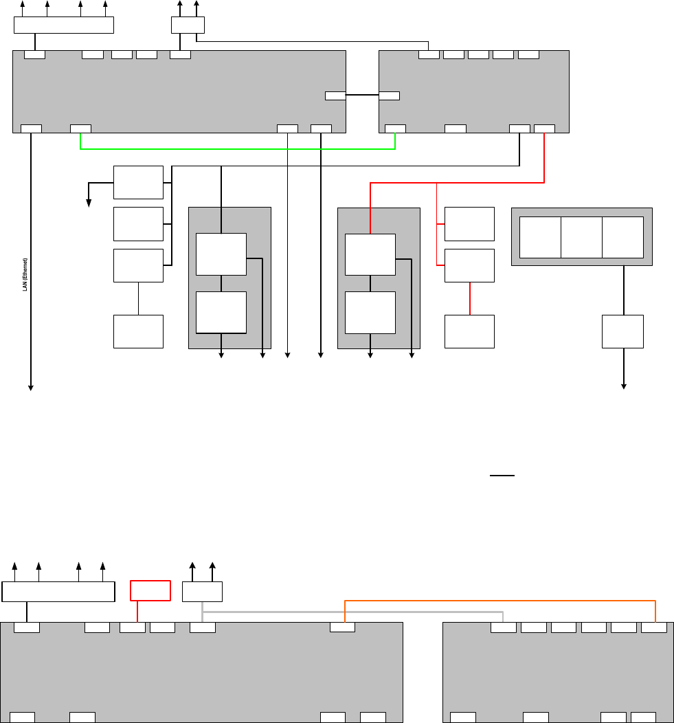
The following diagram shows the hardware components of the computer system for the D-series machine
types (except SIPLACE D3):
Structure of the computer unit with its interfaces
SIPLACE D1 / D2 / D4
LAN connection
Main switch
Line filter
Power connection
Power connection
Voltages
Protection
circuits
Fuses
Measuring
systems
Power supply
Station computer
SIMATIC Box PC 627
Pentium M 2 GHz, 1 GByte RAM, 40 GB HD,
2 x 100 MBit LAN, Graphics, 4 x USB, 1 x serial, 2 PCI slots
PCI 1: 1st hotlink
PCI 2: 2nd hotlink
LAN
VGA
Cameras
( 4 x component camera,
4 x PCB camera )
Measuring systems
Servo amplifiers
4 x X/Y
8 x head
Axis unit 2
USB1
VideoMux
Motors
Axes
( 3 x A364 )
12 axes
Servo amplifiers
4 x X/Y
8 x head
USB2 USB3 USB4
Hotlink Hotlink
Machine controller
SIMATIC Microbox 420
Pentium III, 933 MHz, 256 MByte RAM, 40 GB HD
2 x 100 MBit LAN, Graphics, 4 x USB, 1x serial, 3 x PC104
1st PC104: CAN bus ( 2x )
CAN 1
VGA
LAN 1
USB1
17 of 62
CAN 2
USB2
COM1
USB3 USB4
LAN 2
Motors
Processing area 1 Processing area 2
Monitor
1 2
Keyboard / Touchscreen
1 2
1 MBit/s
500 kBit/s
1 MBit/s
500 kBit/s
Axis unit 1
100 MBit/s
LAN
USB hub
COM1
Conveyor controller
PCB barcode
Gantries
Heads
1 / 2
Gantries
Heads
2 / 4
Axes
( 3 x A364 )
12 axes
I/O module 1 I/O module 2
Component tables 1
/ 4
Tape cutters 1 / 4
Component tables 2
/ 3
Tape cutters 2 / 3
Fig. 3-2: Hardware components of the computer system for the SIPLACE D series except SIPLACE D3 (schematic block diagram)
The following diagram shows the hardware components for the computer system with a configured
coplanarity sensor:
Station computer
SIMATIC Box PC 627
Pentium M 2 GHz, 1 GByte RAM, 40 GB HD,
2 x 100 MBit LAN, Graphics, 4 x USB, 1 x serial, 2 PCI slots
PCI 1: 1st hotlink
PCI 2: 2nd hotlink
LAN
VGAUSB1
Video
multiplexer
USB2 USB3 USB4
Hotlink Hotlink
Machine controller
SIMATIC Microbox 420
Pentium III, 933 MHz, 256 MByte RAM, 40 GB HD
2 x 100 MBit LAN, Graphics, 4 x USB, 1x serial, 3 x PC104
1st PC104: CAN bus ( 2x )
CAN 1
VGA
LAN 1
USB1
CAN 2
USB2 COM1USB3 USB4
LAN 2
Monitor
1 2
LAN
USB hub
Keyboard / Monitor / Touchscreen / Barcode
1 2
COM1
serial
Structure of the computer unit with
3D coplanarity sensor
SIPLACE D3
Coplanarity
sensor
Fig. 3-3: Hardware components of the computer system for the SIPLACE D3 with 3D coplanarity sensor - schematic block diagram

Installation Manual, Station Software Version 603.01 Issue 11/2006
18 of 62
3.3.1 Station computer
Name SIMATIC Box PC 627
CPU / clock frequency Pentium M / 2 GHz
RAM 1 GB
Hard disk 40 GB
External DVD drive Yes
Serial interfaces 1
USB interfaces
and external USB hub
Yes
Network 2x 100 MBit
Table 3-8: Station computer hardware (SIPLACE D series)
3.3.2 Machine controller
Name
SIMATIC Microbox 420
CPU / clock frequency
Pentium III / 933 MHz
RAM
256 MB
Hard disk
40 GB
External DVD drive Yes
Serial interfaces 1
USB interfaces
and external USB hub
Yes
Network
2x 100 MBit
Table 3-9: Machine controller hardware (SIPLACE D series)
Installation Manual, Station Software Version 603.01 Issue 11/2006
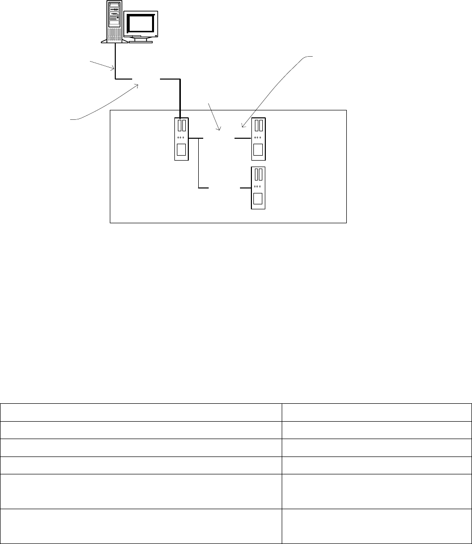
3.4 Network configuration
Station computer
Machine controller
10Base-T
100Base-T
Private network between
station computer,
Vision computer (optional)
and machine controller
SIPLACE LAN
SIPLACE Pro
Twisted Pair TP
(100 MB)
Twisted Pair TP
(10 MB)
Vision computer
(optional)
100Base-T
Fig. 3-4: Network connections between the machine and SIPLACE Pro
A separate private network (100 Mbit) is set up between the station computer (and optionally the Vision
computer) and the machine controller via a subnet mask.
Fixed IP addresses for the station computer, Vision computer and machine controller can thus be assigned
for all SIPLACE machines. These IP addresses are not known outside the private network, for instance in
the SIPLACE LAN or customer LAN.
These IP addresses need not be further configured by the operator while the station software is being
installed.
IP address, station computer 192.168.255.249
IP address, machine controller 192.168.255.250
Vision computer IP Address 192.168.255.251
Subnet mask, station computer/machine controller 255.255.255.248
IP address range, SIPLACE LAN or
IP address range, customer LAN
172.22.xxx.xxx
is configured on-site
Subnet mask for SIPLACE-LAN or
subnet mask for customer LAN
255.255.0.0
is configured on-site
Table 3-10: Network configuration
19 of 62