SOM-1732-001.pdf - 第25页
9 . 3 Electrical Circuit Diagram 9.3.1 Integrated Block Connection Diagram (TCM-X100/-X200/-X300) 9.3 Electrical Circuit Diagram S The -marked areas are specially specified. S Camera for Low Magnification 100 V AC Supply…
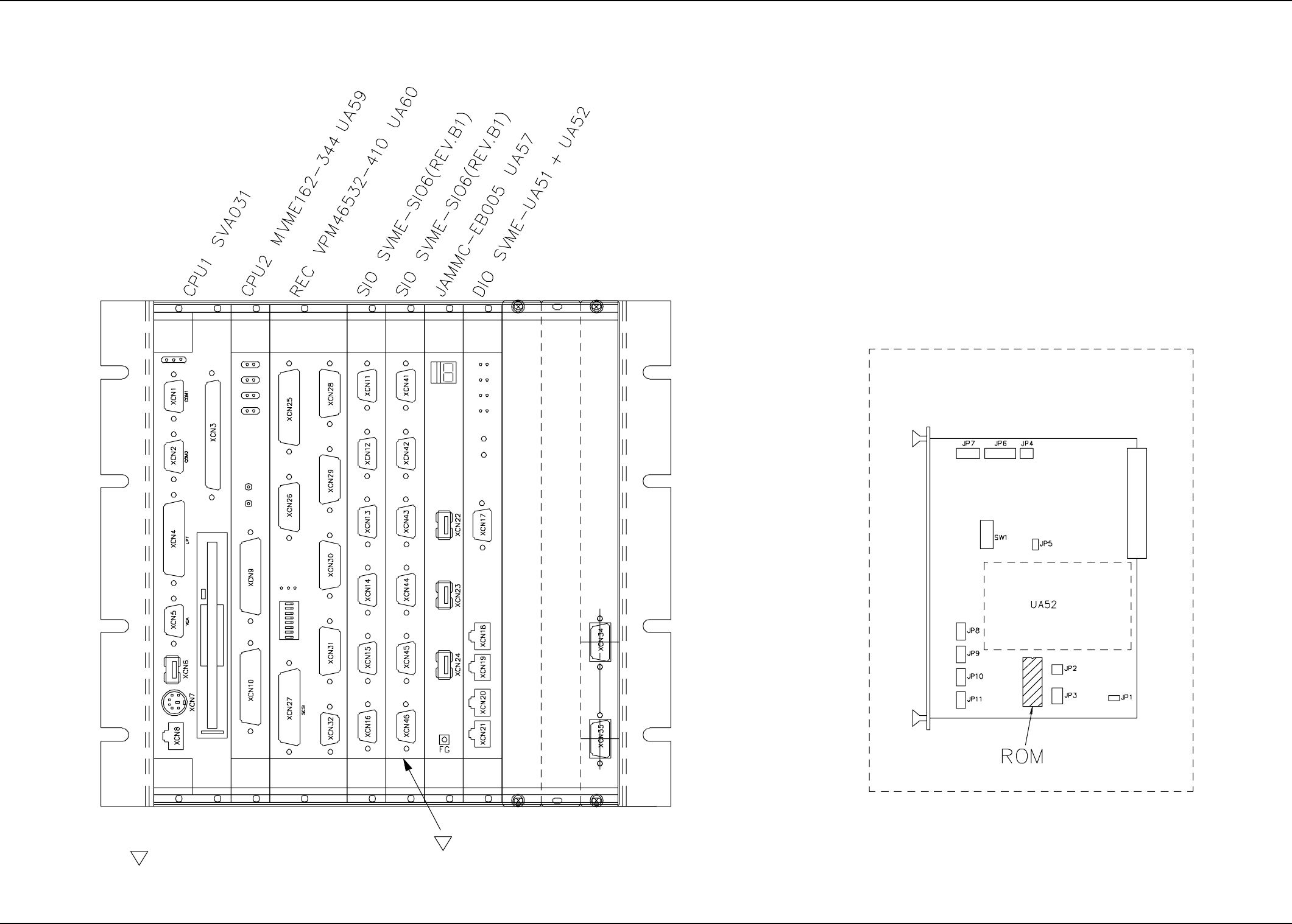
9.2.3 Layout of Control Board (TCM-X100/-X200/-X300, TCM-X110/-X210/-X300)
9.2 Parts Location
S
S
The -marked areas are specially specified.
Component-Mounted Side
Reserved
Reserved
Reserved
ROM Position on UA51 Board
Board
0310-001 -(M696YRH-A1005) 23 AIP01EGP
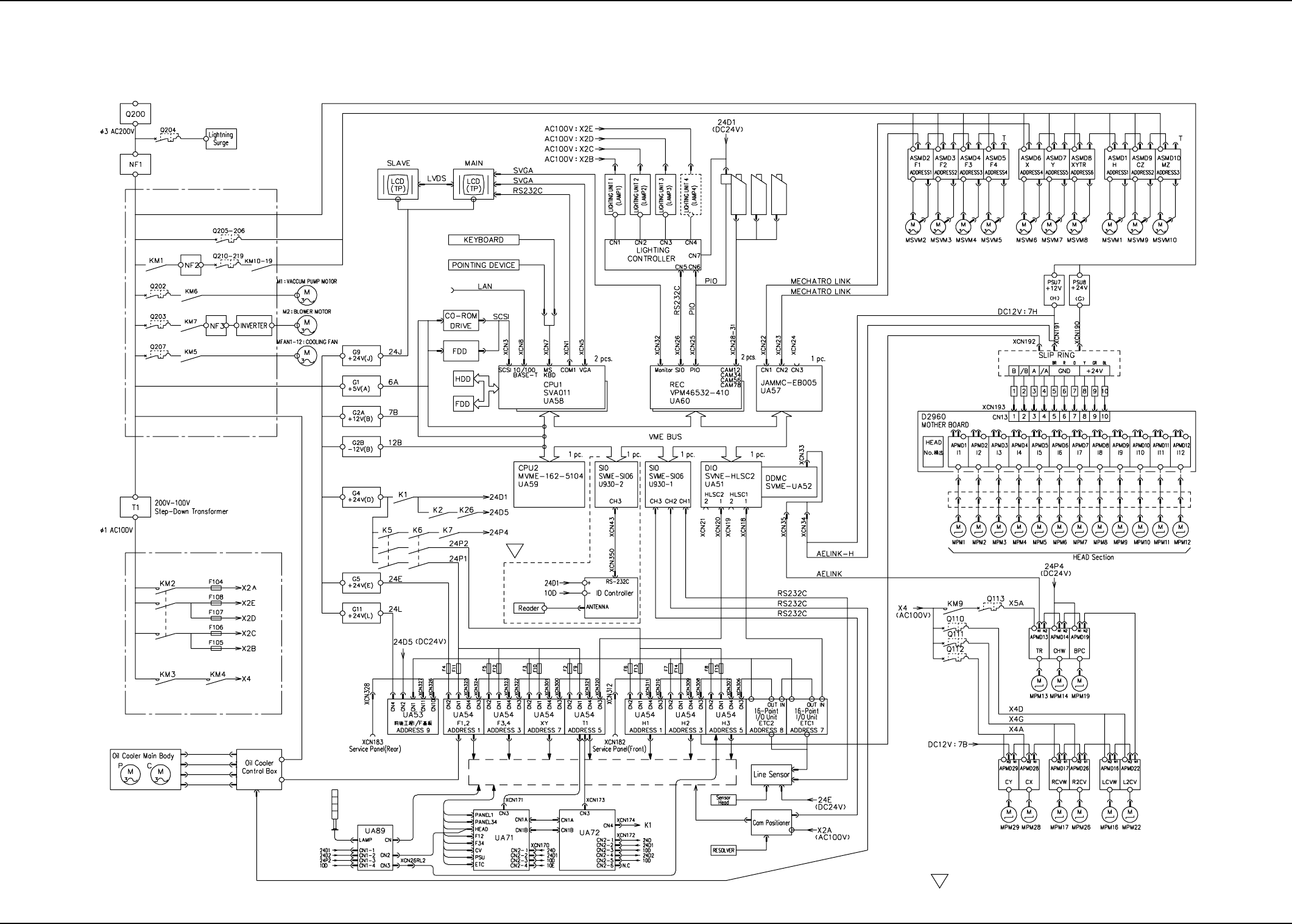
9.3 Electrical Circuit Diagram
9.3.1 Integrated Block Connection Diagram (TCM-X100/-X200/-X300)
9.3 Electrical Circuit Diagram
S
The -marked areas are specially specified.
S
Camera for Low
Magnification
100 V AC Supply Circuit
200 V AC Supply Circuit
Power Supply for
Servomotor Driver
Control
Main Power Supply
for Servomotor
Driver
Loads and Sensors in Each Block
P.E.C. Recog-
nition Camera
Camera for High
Magnification
0310-001 -(M696WA--A1002) 24 AIP01EGP
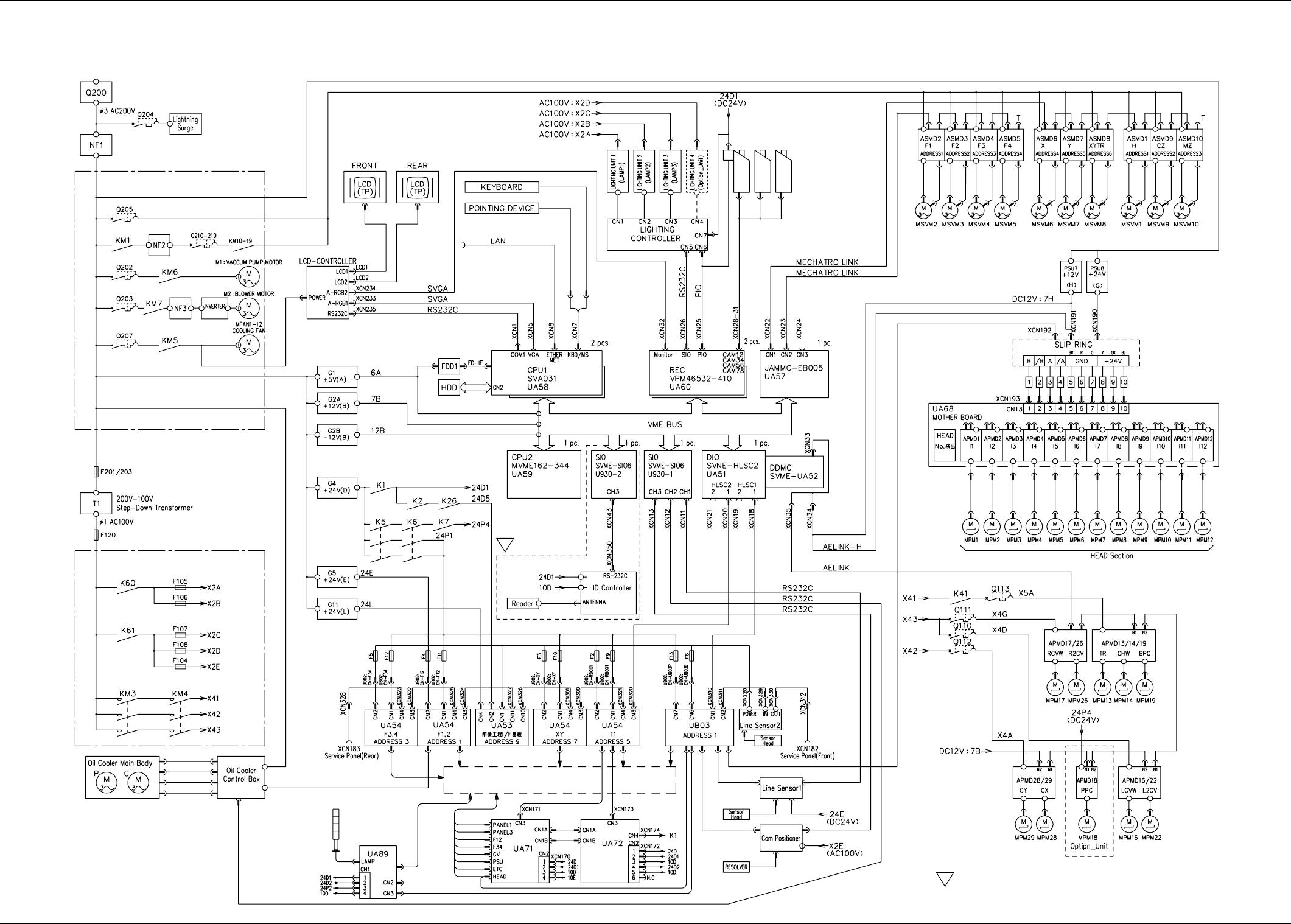
9.3.2 Integrated Block Connection Diagram (TCM-X110/-X210/-X300)
9.3 Electrical Circuit Diagram
S
S
The -marked areas are specially specified.
Camera for Low
Magnification
100 V AC Supply Circuit
200 V AC Supply Circuit
Power Supply for
Servomotor Driver
Control
Main Power Supply
for Servomotor
Driver
Loads and Sensors in Each Block
P.E.C. Recog-
nition Camera
Camera for High
Magnification
0310-001 -(M801WA--A1001) 25 AIP01EGP