00191374-04.pdf - 第103页
Adjus t ment In str uc tio ns SI PLA CE HS- 50 6 Gantries Edition 12/00 6.1 Track Signals 103 NOTE If you adj usted the read h ead corre ctly , the following illustrati on wil l appear on the sc reen of t he oscill osco …

6 Gantries Adjustment Instructions SIPLACE HS-50
6.1 Track Signals Edition 12/00
102
0HDVXULQJ6HTXHQFH
Å Turn the main switch to "ON".
Å Connect the track signal tester to the incremental encoder 1 of the x- / y- axis.
(See
fig 6.1 - 1).
NOTE
The testing sequences of the x- and y- axes are identical.
2VFLOORVFRSH6HWWLQJV
Å Connect the oscilloscope to the track signal tester.
Å Set the oscilloscope to the values of the table below.
&DOLEUDWLRQRI2VFLOORVFRSH
Å Set the track signal tester to selector switch "Oscilloscope cal.".
Å With the help of the positioning switch of CH 1, set the direct current signal on the center of the
upper half of the screen.
0HDVXULQJWKH=HUR3XOVH
Å Set the oscilloscope to the value of the table below:
Å Set the track signal tester to position "Signal output".
Å Manually, move the appropriate axis (x = head / y = gantry) back and forth.
&KDQQHO 6LJQDO &RXSOLQJ <'HIHOFWLRQ 7ULJJHU ;'HIOHFWLRQ
CH 1
"Oscilloscope
cal."
zero pulse DC 0.5 V/ DIV auto 20 ms
&KDQQHO 6LJQDO &RXSOLQJ <'HIOHFWLRQ 7ULJJHU ;'HIOHFWLRQ
CH 1
signal output zero pulse DC 0.5 V/ DIV
2.5V norm
pre- trig. 50%
20 ms
Adjustment Instructions SIPLACE HS-50 6 Gantries
Edition 12/00 6.1 Track Signals
103
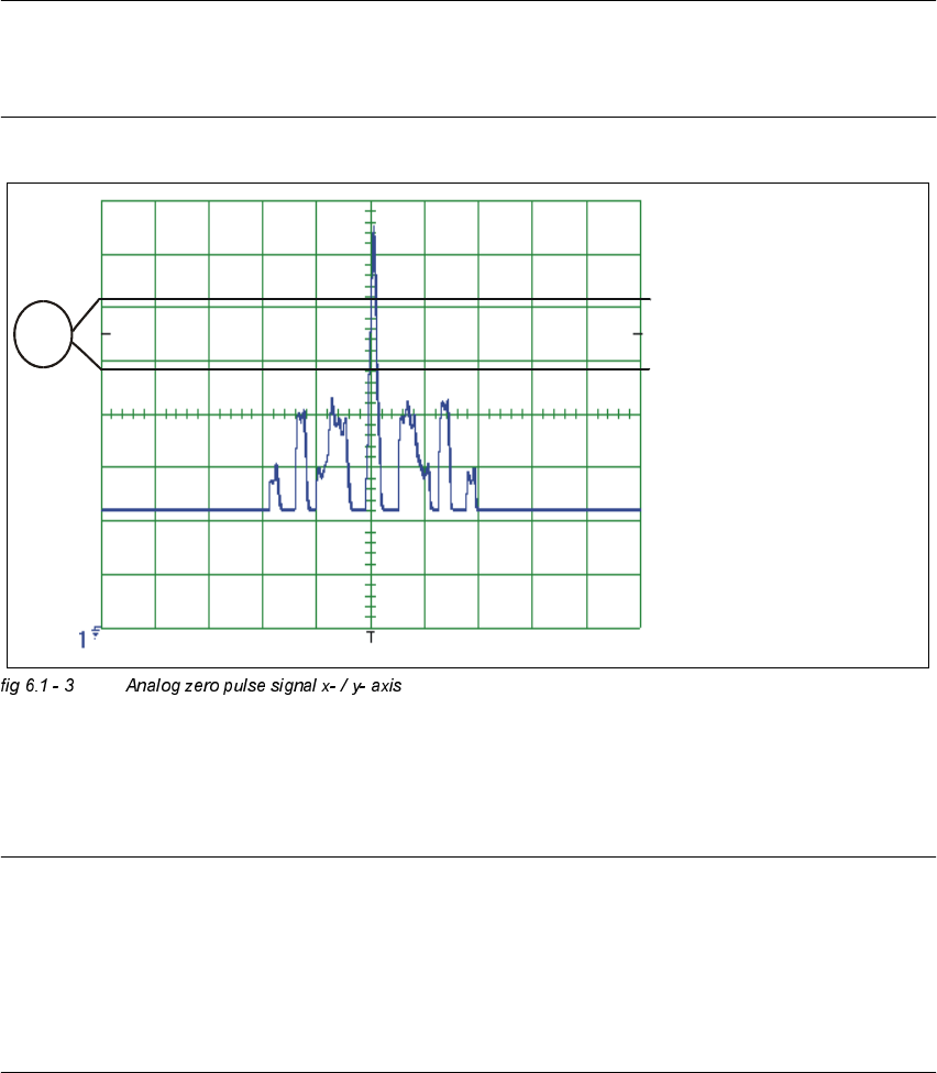
NOTE
If you adjusted the read head correctly, the following illustration will appear on the screen of the
oscilloscope:
.(<
(1) No spurious peaks are allowed in this measuring range.
NOTE
Check the analog signal of the zero pulse, to ascertain that the zero pulse is discerned correctly.
If the zero pulse is not discerned correctly, the axis will reference to a spurious peak.
Placement offsets will be the result.
The pulse width of the analog zero pulse is dependent on the speed at which the axis is
traversed.
CH1
6 Gantries Adjustment Instructions SIPLACE HS-50
6.1 Track Signals Edition 12/00
104
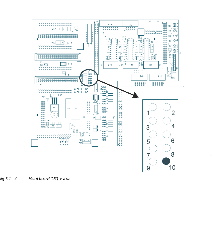
7UDFN6LJQDOVRI*DQWU\$[HV
0HDVXUHPHQWRI7UDFN6LJQDOVRI;$[HV&RQQHFWRU;RQ+HDG%RDUG&
.(<
; = x-axis
Pin configuration
;
1. Ground 2. Track A
3. Track A
4. Ground
5. Track B 6. Track B
7. Track N 8. Track N
9. -4V 10.removed