00191374-04.pdf - 第105页
Adjus t ment In str uc tio ns SI PLA CE HS- 50 6 Gantries Edition 12/00 6.1 Track Signals 105 0HDVXULQJ7 UDF N6LJQ DOVRIWKH < $[HV&R QQHFWRU; R Q;< 'LVWULEXWRU6 .(< ; = y-a…
6 Gantries Adjustment Instructions SIPLACE HS-50
6.1 Track Signals Edition 12/00
104
7UDFN6LJQDOVRI*DQWU\$[HV
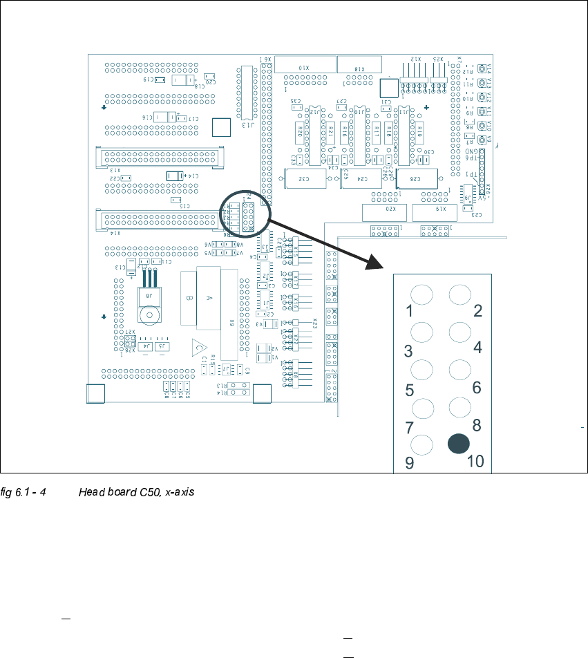
0HDVXUHPHQWRI7UDFN6LJQDOVRI;$[HV&RQQHFWRU;RQ+HDG%RDUG&
.(<
; = x-axis
Pin configuration
;
1. Ground 2. Track A
3. Track A
4. Ground
5. Track B 6. Track B
7. Track N 8. Track N
9. -4V 10.removed
Adjustment Instructions SIPLACE HS-50 6 Gantries
Edition 12/00 6.1 Track Signals
105
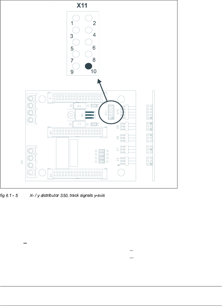
0HDVXULQJ7UDFN6LJQDOVRIWKH<$[HV&RQQHFWRU;RQ;<'LVWULEXWRU6
.(<
; = y-axis
Pin configuration:
NOTE
At present, there is no adapter available. Therefore, track signals must be measured at the pins.
1. Ground 2. Track A
3. Track A
4. Ground
5. Track B 6. Track B
7. Track N 8. Track N
9. -4V 10.removed
6 Gantries Adjustment Instructions SIPLACE HS-50
6.1 Track Signals Edition 12/00
106
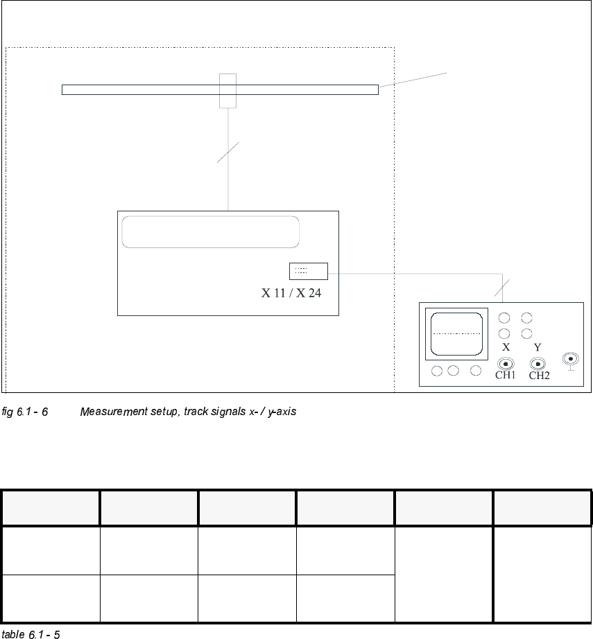
0HDVXUHPHQW6HWXS
2VFLOORVFRSH6HWWLQJV
3URFHGXUH
Å Turn on the machine.
Å Connect both channels to connector X11, or X24 respectively, to pin 1.
Å Set the oscilloscope to the settings of the table above.
Å With the help of the positioning switch CH1, move the light spot of the oscilloscope exactly to
the center of the crosshairs of the screen.
ELOGEHVVHUQ
Messsystem X- / Y- Achse /
measuring system x- / y- axis
Spur A / B / RI /
track A / B / RI
Platine C 40 / C 50 /
board C 40 / C 50
6,3/$&(+6
BNC - Leitung /
BNC line
Auflösung des Maßstabes: 1 Digit = 1
measuring scale: 1 dgt = 1 m
µ
&KDQQHO 6LJQDO &RXSOLQJ <'HIOHFWLRQ 7ULJJHU ;'HIOHFWLRQ
CH 1 track A of X11
or X24 pin2
DC 2 V/ DIV
auto 5 ms
CH 2 track B of X11
or X24 pin5
DC 2 V/ DIV