00191374-04.pdf - 第107页
Adjus t ment In str uc tio ns SI PLA CE HS- 50 6 Gantries Edition 12/00 6.1 Track Signals 107 Å With the hel p of the positio ning switc h CH2, move the lig ht spot of the oscil loscope exa ctly to the l owe r edg e of t…
6 Gantries Adjustment Instructions SIPLACE HS-50
6.1 Track Signals Edition 12/00
106
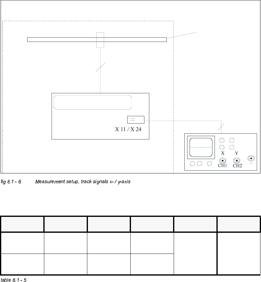
0HDVXUHPHQW6HWXS
2VFLOORVFRSH6HWWLQJV
3URFHGXUH
Å Turn on the machine.
Å Connect both channels to connector X11, or X24 respectively, to pin 1.
Å Set the oscilloscope to the settings of the table above.
Å With the help of the positioning switch CH1, move the light spot of the oscilloscope exactly to
the center of the crosshairs of the screen.
ELOGEHVVHUQ
Messsystem X- / Y- Achse /
measuring system x- / y- axis
Spur A / B / RI /
track A / B / RI
Platine C 40 / C 50 /
board C 40 / C 50
6,3/$&(+6
BNC - Leitung /
BNC line
Auflösung des Maßstabes: 1 Digit = 1
measuring scale: 1 dgt = 1 m
µ
&KDQQHO 6LJQDO &RXSOLQJ <'HIOHFWLRQ 7ULJJHU ;'HIOHFWLRQ
CH 1 track A of X11
or X24 pin2
DC 2 V/ DIV
auto 5 ms
CH 2 track B of X11
or X24 pin5
DC 2 V/ DIV
Adjustment Instructions SIPLACE HS-50 6 Gantries
Edition 12/00 6.1 Track Signals
107
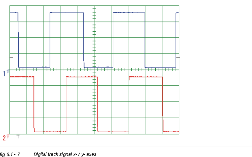
Å With the help of the positioning switch CH2, move the light spot of the oscilloscope exactly to
the lower edge of the screen.
Å Swap CH1 to connector X11, or X24 respectively, to pin 2.
Å Swap CH2 to connector X11, or X24 respectively, to pin 5.
Å Manually, move the appropriate axis back and forth.
– If you adjusted read head correctly, the following illustration will appear on the screen of the
oscilloscope:
Spur A / track A
Spur B / track B
6 Gantries Adjustment Instructions SIPLACE HS-50
6.2 Zero Point Corrections Edition 12/00
108
=HUR3RLQW&RUUHFWLRQV
Setting of the zero point corrections will be determined with machine calibration.
Compare the chapter "Zero Point Calibration of Machine" .