00191374-04.pdf - 第109页
Adjus t ment In str uc tio ns SI PLA CE HS- 50 6 Gantries Edition 12/00 6.3 Mechanical Settings 109 0 HFKDQ LFDO6HWWLQJV %HOW7 HQVLRQRI;$[LV 0 HDVXULQJ 'DW DDQG$L GLQJ7 RROV 0 HDVX…
6 Gantries Adjustment Instructions SIPLACE HS-50
6.2 Zero Point Corrections Edition 12/00
108
=HUR3RLQW&RUUHFWLRQV
Setting of the zero point corrections will be determined with machine calibration.
Compare the chapter "Zero Point Calibration of Machine" .
Adjustment Instructions SIPLACE HS-50 6 Gantries
Edition 12/00 6.3 Mechanical Settings
109
0HFKDQLFDO6HWWLQJV
%HOW7HQVLRQRI;$[LV
0HDVXULQJ'DWDDQG$LGLQJ7RROV
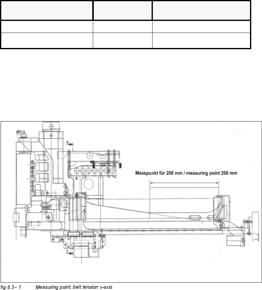
0HDVXULQJ6HTXHQFH
Å Move the x-slide against the stop on the motor side.
Å Measure the belt tension on the side of the placement head.
Å Center the measuring pin of the belt tension measuring device, 208 mm away from the
deflection pulley of the open ended toothed belt, as close as possible to the belt.
%HOW%UDQGQHZ %HOW6KUXQNDIWHUDSSUR[
KRXUVRIRSHUDWLRQ
toothed belt to be measured frequency (Hz) frequency (Hz)
at the x-axis (open ended) 53 Hz +1 / -3 Hz 53 Hz +1 / -3 Hz
6 Gantries Adjustment Instructions SIPLACE HS-50
6.3 Mechanical Settings Edition 12/00
110
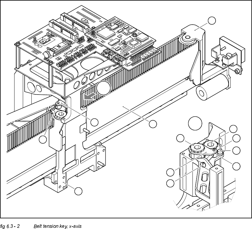
.(<
(A) Detail, zoom
(1) Chuck key
(2) Chuck key
(3) Head screw M4 x 35 to tension the toothed belt
(4) Head mounting
(5) Toothed belt of x-axis
(6) Deflection unit X
(7) Spacer disk with Benzing-U-Clip
(8) Head screw M4 x 5
(9) Synchronizing disk, short
(10) Synchronizing disk, long
A
A
1
8
7
9
10
2
3
1
2
4
5
6