00191374-04.pdf - 第119页
Adjus t ment In str uc tio ns SI PLA CE HS- 50 6 Gantries Edition 12/00 6.5 Dynamic A djustment of the X - and Y- A xes 119 '\ QDPL F$G MXVWP HQW RIWK H;DQG< $[HV NOTE Gantry 1 s erves to exempl ify …

6 Gantries Adjustment Instructions SIPLACE HS-50
6.4 Settings and Illustrations Edition 12/00
118
3UR[LPLW\VZLWFK; 3UR[LPLW\VZLWFK;
gantry 1 top bottom
gantry 2 bottom top
gantry 3 top bottom
gantry 4 bottom top
distance sensor X9 only with gantry 1 and 3
6ZLWFKSRLQWV5HIHUHQFHHQGSRVLWLRQ
1 switch point: end position gantry 2 , 4
2 switch point: reference gantry 2, 4
3 switch point: reference gantry 1, 3
4 switch point: end position gantry 1, 3
Adjustment Instructions SIPLACE HS-50 6 Gantries
Edition 12/00 6.5 Dynamic Adjustment of the X- and Y- Axes
119
'\QDPLF$GMXVWPHQWRIWKH;DQG<$[HV
NOTE
Gantry 1 serves to exemplify all SITEST functions.
(TXLSPHQWDQG7HVW'HYLFHV
– 2 or 4 channel storage oscilloscope.
– SIPLACE axis test box, complete.
– SITEST software.
NOTE
The machine must have reached its operating temperature before you begin to adjust the axes.
Therefore, make sure to switch it on, at least 30 minutes before you begin to work.
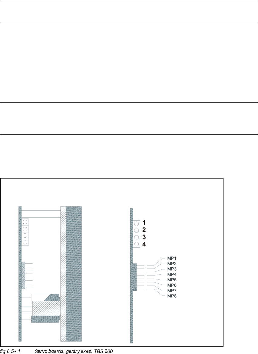
6HUYR%RDUGV*DQWU\$[HV+6
TBS 200 / 10X
TBS 200 / 15Y

6 Gantries Adjustment Instructions SIPLACE HS-50
6.5 Dynamic Adjustment of the X- and Y- Axes Edition 12/00
120
.(<
TBS 200 / 10X = Servo board x-axis
TBS 200 / 15Y = Servo board y-axis
(1) LED: Ready for operation
(2) LED: Servo enable
(3) LED: I
RMS
limit
(4) LED: Error
MP1 = Nominal current "I-S (U)"
MP2 = Nominal current "I-S (W)"
MP3 = Actual current "I-ist (U)"
MP4 = Actual current "I-ist (W)"
MP5 = "U-nominal (U)"
MP6 = "U-nominal (W)"
MP7 = Free
MP8 = Reference potential "0V"
NOTE
For a proper triggering connect the endsignal and the nominal current.