00191374-04.pdf - 第124页
6 Gantries Adjust men t Ins tru ct ion s SIPL ACE H S-50 6.5 Dynamic Adjustment of the X- and Y- Axes Edition 12/00 124 2VFLOORV FRSH6 HWWLQJV &KDQQHO 6LJQD O &R X SO LQJ < ' H I O H F W L R Q 7 U…
Adjustment Instructions SIPLACE HS-50 6 Gantries
Edition 12/00 6.5 Dynamic Adjustment of the X- and Y- Axes
123
&RQWURORIWKH;$[LV'\QDPLFV
*HQHUDO3UHSDUDWLRQV
Å Make sure that the belt tension is correctly adjusted to 53 Hz +1 / -3 Hz.
Å Start SITEST.
Å Switch on the compressed air supply.
Å Make sure that all friction surfaces are clean.
Å Prepare the measurement setup for the x-axis. (See fig 6.5 - 3).
Å Set the oscilloscope according to the values of the table below.
Å Perform a head reference run.
Å Perform a gantry reference run.
NOTE
Use an RC - filter to record the current curve.
Measure the end signal on the adapter board "axis test box", with the switch pressed down.
&RQWURO3*DLQ
NOTE
Adjustment of the gantry axes on the servo amplifier is not possible.
Adjustment parameters are preset through board VC10.
This board is positioned on the axis control cards 1, 2, 3 and 4.
The nominal current of the x-axis must be measured at the "measuring adapter axis control card,
measuring pin axis 0".
(Do not connect GND).
6,7(67
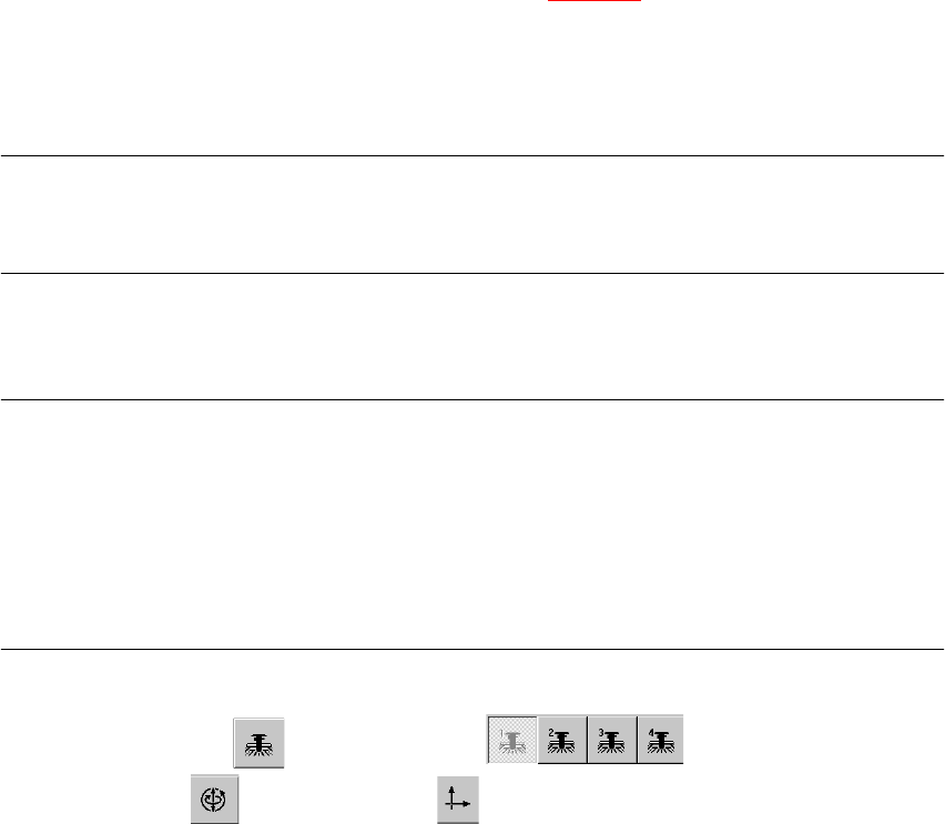
Å Select "Gantry" ==> ==> "Select gantry" ==>
"Axis functions" ==> "Select x-axis" ==> "Adjust P-gain" ==>
"Select travel range with the help of the ÇÆ arrow buttons" ==> "End" ==> "Abort".
6 Gantries Adjustment Instructions SIPLACE HS-50
6.5 Dynamic Adjustment of the X- and Y- Axes Edition 12/00
124
2VFLOORVFRSH6HWWLQJV
&KDQQHO 6LJQDO &RXSOLQJ <'HIOHFWLRQ 7ULJJHU ;'HIOHFWLRQ
CH1 Vnominal DC 0.1 V/ DIV
CH 1
positive
10% pre
10 ms/ DIV
CH2 deviat. of pos. DC 0.5 V/ DIV
CH3 nominal current DC 0.2 V/ DIV
Ch4 end signal DC 5.0 V/ DIV
&KDQQHO 6LJQDO &RXSOLQJ <'HIOHFWLRQ 7ULJJHU ;'HIOHFWLRQ
CH1 Vnominal DC 1.0V/ DIV
CH 1
positive
3% pre
10 ms/ DIV
CH2 deviat. of pos. DC 0.5 V/ DIV
CH3 nominal current DC 5.0V/ DIV
Ch4 end signal DC 5.0 V/ DIV
Adjustment Instructions SIPLACE HS-50 6 Gantries
Edition 12/00 6.5 Dynamic Adjustment of the X- and Y- Axes
125
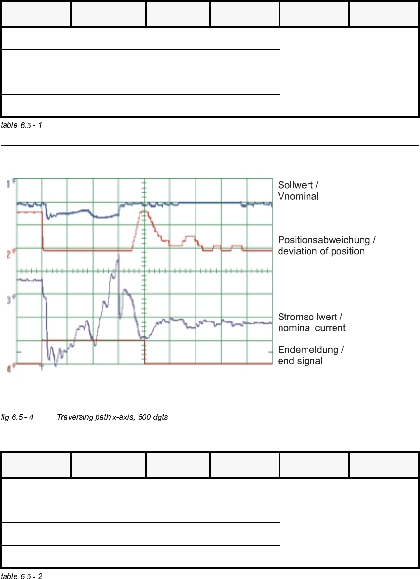
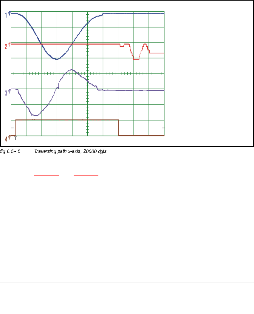
– If you adjusted the dynamics of the x-axis correctly, each individual signal will be displayed as
shown in fig 6.5 - 4
. and fig 6.5 - 5.
<$[LV
*HQHUDO3UHSDUDWLRQ
Å Start SITEST.
Å Make sure that all friction surfaces are clean.
Å Prepare the measurement setup for the y-axis. (See fig 6.5 - 3).
Å Perform a head reference run.
Å Perform a gantry reference run.
NOTE
Use an RC - filter to record the current curve
Measure the end signal on the adapter board "axis test box", with the switch pressed down.
Sollwert /
Vnominal
Positionsabweichung /
deviation of position
Kraftsollwert /
nominal current
Endemeldung /
end signal