00191374-04.pdf - 第138页
7 Collect & Place Head DLM1 Adjustment Instructions SIPLACE HS-50 7.1 Track Si gnals Edition 12/00 138 3URFHGXUH Å T urn on the machi ne. Å Conn ect both c hannels to the con nectors X13, X15 or X1 6 , pin1 r…
Adjustment Instructions SIPLACE HS-50 7 Collect & Place Head DLM1
Edition 12/00 7.1 Track Signals
137
7HVW6HWXS
NOTE
At present, there is no measuring adapter available. Therefore, the track signals can only be
measured on the pins.
2VFLOORVFRSH6HWWLQJV
12
3
4
5
6
78
9
10
X
CH1
CH2
EXT
X13 / X15 / X16
&KDQQHO 6LJQDO &RXSOLQJ <'HIOHFWLRQ &KDQQHO 6LJQDO
CH1
track A of X13,
X15 o r X16,
pin 2 resp.
DC 1.0 V / DIV CH1
track A of X13,
X15 o r X16,
pin 2 resp.
CH2
track B of X13,
X15 or X16 pin
5 resp.
DC 1.0 V/ DIV CH2
track B of X13,
X15 or X16 pin
5 resp.
7 Collect & Place Head DLM1 Adjustment Instructions SIPLACE HS-50
7.1 Track Signals Edition 12/00
138
3URFHGXUH
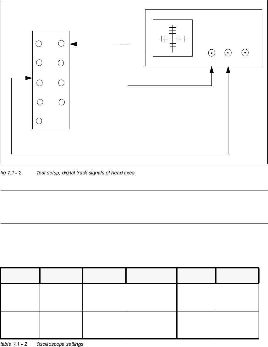
Å Turn on the machine.
Å Connect both channels to the connectors X13, X15 or X16, pin1 respectively.
Å Set the oscilloscope to "auto" (with trigger).
Å With the help of the positioning switches of CH1 and CH2, move the oscilloscope ray of CH1
to the center of the screen and the oscilloscope ray of CH2 to the lower edge of the screen.
Å Change the connection of CH1 to connector X13, X15 or X16 on pin 2 respectively.
Å Change the connection of CH2 to connector X 13, X15 or X16 on pin 5 respectively.
Å Set the trigger to "norm" and set the oscilloscope with "trigger" to a suitable triggering
threshold.
Å Manually, move the appropriate axis back and forth.
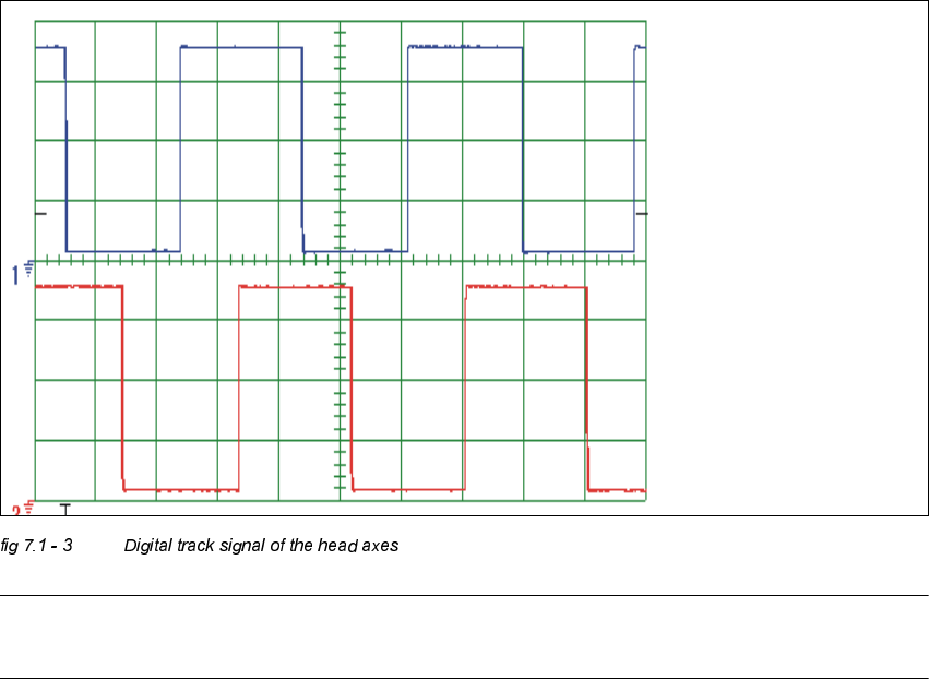
– If you adjusted the read correctly, the following illustration will be displayed on the
oscilloscope screen:
NOTE
Pulse width is dependent on the speed, the phase location is dependent on the direction.
Spur A / track A
Spur B / track B
Adjustment Instructions SIPLACE HS-50 7 Collect & Place Head DLM1
Edition 12/00 7.2 Zero Point Corrections
139
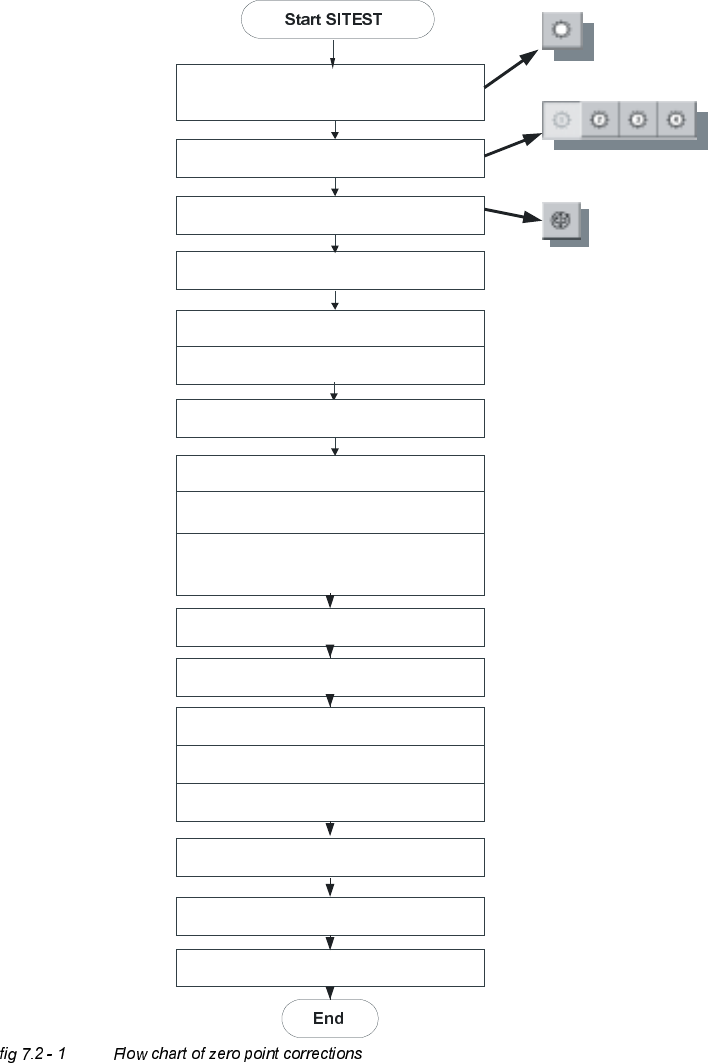
=HUR3RLQW&RUUHFWLRQV
'HWHUPLQDWLRQRI=HUR3RLQW&RUUHFWLRQ6WDU$[LV&ROOHFW3ODFH+HDG
C&P Heads
Axes
Positions
Select star - axis
Select appropriate head
Zero point corrections = 0
edit and accept
Axis reference run
Axis enable
Rotate segment 1 downward,
place gauge for the star, insert pin
Take sleeve out of star position 1
Select the dp-axis and again the star-axis
Note actual position as new
zero point correction
Connect servo
Remove gauge for the star
Insert sleeve
Check zero point corrections
(segment 1, on the bottom)
Save machine data
Axis reference run