00191374-04.pdf - 第139页
Adjustment I nstructions SIP LACE HS-50 7 Collect & Place Head DLM1 Edition 12/00 7. 2 Zero Point Corrections 139 = HUR3RLQW&RUUHFWLRQV 'HWHUPLQDWLRQRI=HU R3RLQW&RUUHFWLRQ6 WDU$[LV &…
7 Collect & Place Head DLM1 Adjustment Instructions SIPLACE HS-50
7.1 Track Signals Edition 12/00
138
3URFHGXUH
Å Turn on the machine.
Å Connect both channels to the connectors X13, X15 or X16, pin1 respectively.
Å Set the oscilloscope to "auto" (with trigger).
Å With the help of the positioning switches of CH1 and CH2, move the oscilloscope ray of CH1
to the center of the screen and the oscilloscope ray of CH2 to the lower edge of the screen.
Å Change the connection of CH1 to connector X13, X15 or X16 on pin 2 respectively.
Å Change the connection of CH2 to connector X 13, X15 or X16 on pin 5 respectively.
Å Set the trigger to "norm" and set the oscilloscope with "trigger" to a suitable triggering
threshold.
Å Manually, move the appropriate axis back and forth.
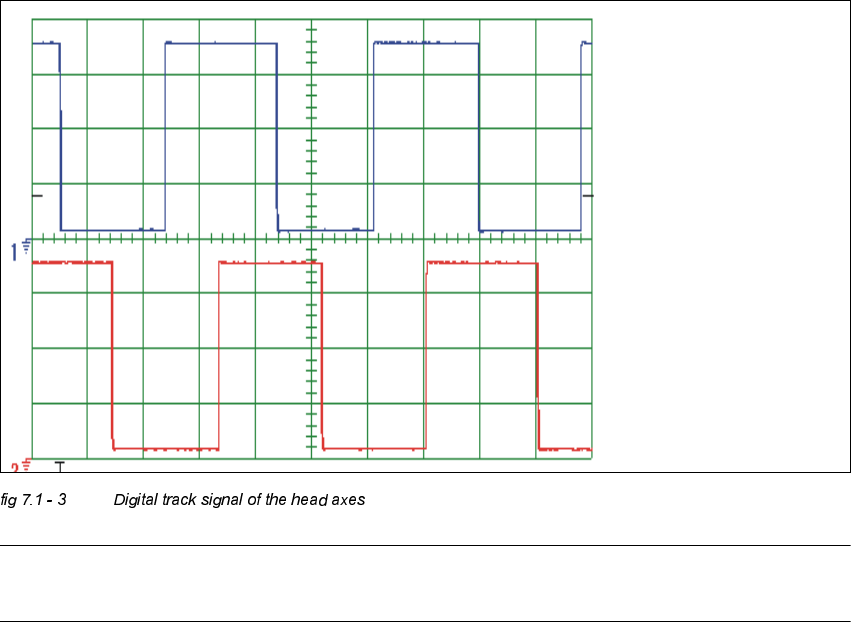
– If you adjusted the read correctly, the following illustration will be displayed on the
oscilloscope screen:
NOTE
Pulse width is dependent on the speed, the phase location is dependent on the direction.
Spur A / track A
Spur B / track B
Adjustment Instructions SIPLACE HS-50 7 Collect & Place Head DLM1
Edition 12/00 7.2 Zero Point Corrections
139
=HUR3RLQW&RUUHFWLRQV
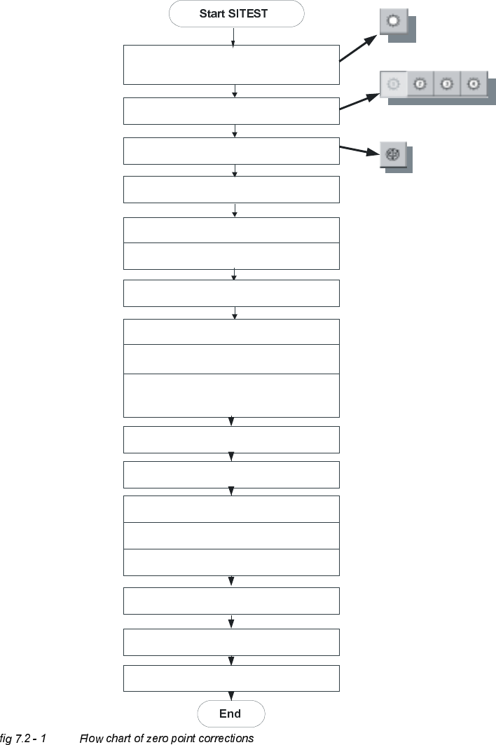
'HWHUPLQDWLRQRI=HUR3RLQW&RUUHFWLRQ6WDU$[LV&ROOHFW3ODFH+HDG
C&P Heads
Axes
Positions
Select star - axis
Select appropriate head
Zero point corrections = 0
edit and accept
Axis reference run
Axis enable
Rotate segment 1 downward,
place gauge for the star, insert pin
Take sleeve out of star position 1
Select the dp-axis and again the star-axis
Note actual position as new
zero point correction
Connect servo
Remove gauge for the star
Insert sleeve
Check zero point corrections
(segment 1, on the bottom)
Save machine data
Axis reference run
7 Collect & Place Head DLM1 Adjustment Instructions SIPLACE HS-50
7.3 Adjustments Edition 12/00
140
$GMXVWPHQWV
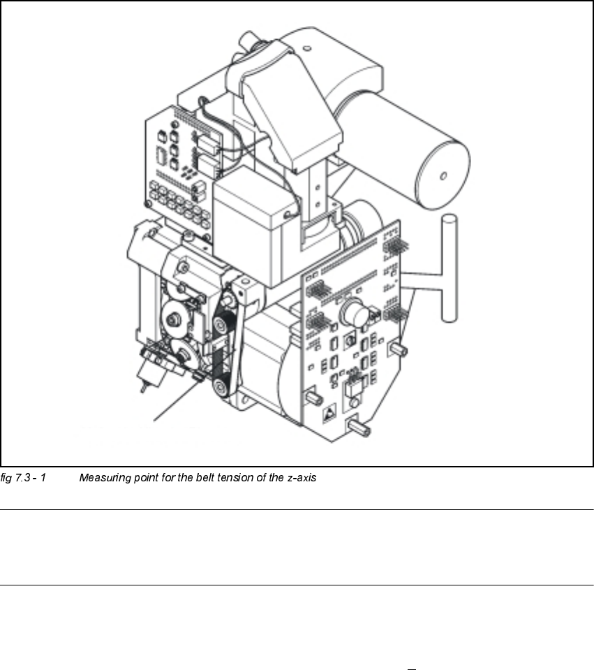
%HOW7HQVLRQRIWKH=$[LV
Å Attach the measuring head in front of the toothed belt.
NOTE
The measuring point of the measuring pin must be in the middle of the two deflection pulleys.
The measuring pin should be at a maximum distance of 2 - 3 mm, from the toothed belt.
Å Strike the toothed belt, to reach a stimulation of vibration of the open ended toothed belt.
Å Stretch the belt over the fastening of the driving motor (compare: service manual) if the
frequency of the belt tension does not reach a value of 280 Hz +
10 Hz.
Å Repeat these instructions until the belt tension is correct.
Messpunkt: Riemenmitte /
measuring point: middle of belt