00191374-04.pdf - 第143页
Adjustment I nstructions SIP LACE HS-50 7 Collect & Place Head DLM1 Edition 12/00 7.3 Adjustments 143 $ LU3 UHVV XU H9 D OXHV 7 RROVDQG'HY LFHV – A set of s lotted s crew driv ers – Compress e…
7 Collect & Place Head DLM1 Adjustment Instructions SIPLACE HS-50
7.3 Adjustments Edition 12/00
142
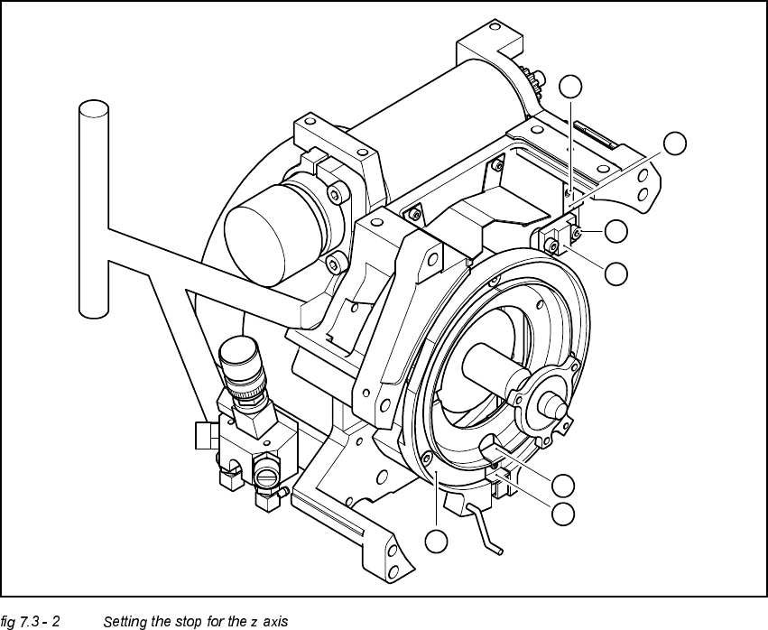
.H\WR)LJ
(1) M2x4 hexagon socket-head screw
(2) Stop piece
(3) 2 x M2.5x8 hexagon socket-head screw
(4) Stop
(5) Snap jaws of the z axis
(6) Raceway
(A) Insert the z axis gauge here
6
A
5
4
3
2
1
Adjustment Instructions SIPLACE HS-50 7 Collect & Place Head DLM1
Edition 12/00 7.3 Adjustments
143
$LU3UHVVXUH9DOXHV
7RROVDQG'HYLFHV
– A set of slotted screw drivers
– Compressed air testing device
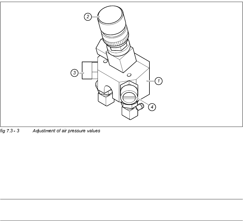
$GMXVWPHQWRI$LU3UHVVXUH9DOXHV
.(<
(1) Forced air unit / DLM1
(2) Micro - relay valve
(3) Restrictor valve for the reject circuit
(4) Restrictor valve for the pick - up / placement circuit
NOTE
Use a nozzle type 914 to adjust the blast air.
7 Collect & Place Head DLM1 Adjustment Instructions SIPLACE HS-50
7.3 Adjustments Edition 12/00
144
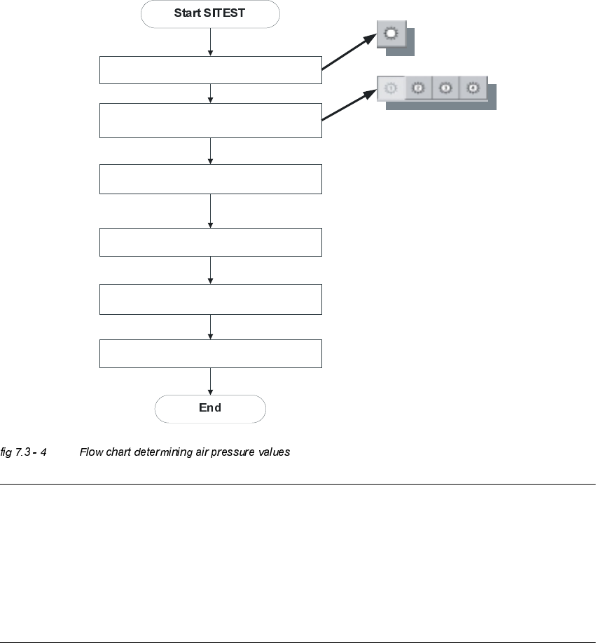
$GMXVWPHQWVRIWKH$LU3UHVVXUH9DOXHVZLWKWKH+HOSRID&RPSUHVVHG$LU7HVWLQJ
'HYLFH
NOTE
Air pressure values, displayed on the screen of the station computer, under option "Measure air
pressure" of the "Single functions", or in the SITEST program, do not correspond to the air
pressure values actually set at the nozzles.
They solely serve to check that the forced air valve is functioning correctly.
Therefore, the air pressure may not be adjusted with the values displayed on the screen.
Instead, use only the values determined with the compressed air testing device.
Blast air “ON”
Placement and pick - up circuit
Select appropriate head
Collect & Place Heads
Use compressed air testing device and
restrictor valve to adjust compressed air
Blast air “OFF”