00191374-04.pdf - 第157页
Adjustment I nstructions SIP LACE HS-50 7 Collect & Place Head DLM1 Edition 12/00 7.4 Dynamic Ad justment of the A xes 157 $GMXVWPHQW RI3* DLQZ LW K&XUUHQW6HQVRU 0 RGH NOTE Adjusti ng the P -gain,…
7 Collect & Place Head DLM1 Adjustment Instructions SIPLACE HS-50
7.4 Dynamic Adjustment of the Axes Edition 12/00
156
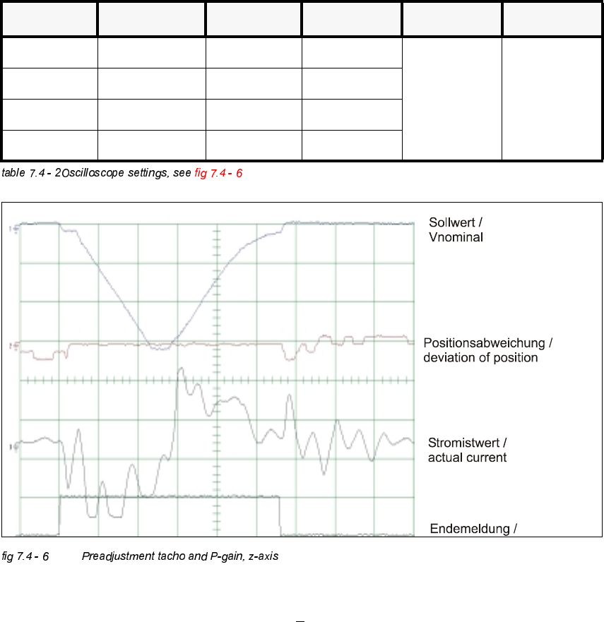
2VFLOORVFRSH6HWWLQJV
– If the dynamics of the star are correct, each signal will appear as illustrated above.
– Nominal - positioning time: 685 dgts: 28 ms +
2 ms.
&KDQQHO 6LJQDO &RXSOLQJ <'HIOHFWLRQ 7ULJJHU ;'HIOHFWLRQ
CH1 Vnominal DC 2.0 V/ DIV
CH1
negative
10% pre
5 ms/ DIV
CH2 deviat. of pos. DC 0.5 V/ DIV
CH3 actual current DC 5.0 V/ DIV
CH4 end signal DC 5.0 V/ DIV
Adjustment Instructions SIPLACE HS-50 7 Collect & Place Head DLM1
Edition 12/00 7.4 Dynamic Adjustment of the Axes
157
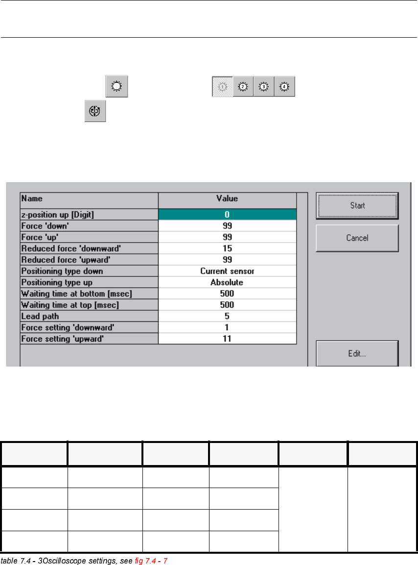
$GMXVWPHQWRI3*DLQZLWK&XUUHQW6HQVRU0RGH
NOTE
Adjusting the P-gain, you may only finely readjust the tacho potentiometer.
6,7(67
Å Select "C&P Heads" ==> "Select head" ==>
"Axis functions" ==> "Select z-axis" ==> "Calibration tool position" ==>
"Adjust P-gain" ==> "Edit values and accept: If necessary, press the START button.
Å If necessary, press the START button.
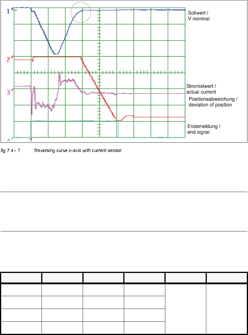
2VFLOORVFRSH6HWWLQJV
&KDQQHO 6LJQDO &RXSOLQJ <'HIOHFWLRQ 7ULJJHU ;'HIOHFWLRQ
CH1 Vnominal DC 1.0 V/ DIV
CH1
negative
0 % pre
10 ms/ DIV
CH2 deviation of pos. DC 1.0 V/ DIV
CH3 actual current DC 5.0 V/ DIV
CH 4 end signal DC 5.0 V/ DIV
7 Collect & Place Head DLM1 Adjustment Instructions SIPLACE HS-50
7.4 Dynamic Adjustment of the Axes Edition 12/00
158
Å Increase the P-gain until an acceptable positioning of the axis becomes possible. Acceptable
means that a clear rounding at the rising edge of the nominal value has formed during transi-
tion to position control.
NOTE
Any oscillation of the current curve must be avoided.
Vnominal must be visibly rounded in the marked area.
(See marked circle in the illustration above).
Å If you adjusted the p-gain, proceed to repeat the adjustment of the tacho (see 7.4.5).
Å Control of P-Gain with Light Barrier ModeOscilloscope Settings
1. Setup oscilloscop, see fig 7.4 - 8 and fig 7.4 - 9
&KDQQHO 6LJQDO &RXSOLQJ <'HIOHFWLRQ 7ULJJHU ;'HIOHFWLRQ
CH1 Vnominal DC 2.0 V/ Div
CH 1
negative
10% pre
5 ms/ Div
CH2 deviat. of pos. DC 1.0 V/ Div
CH3 actual value DC 2.0 V/ Div
Ch4 end signal DC 5.0 V/ Div