00191374-04.pdf - 第167页
9 Calibration of SI PLACE HS-50 (incl. SITE ST version 501.xx) Adjustment Inst ructions SIPLACE HS-50 Softwareversion SR. 501.xx Edition 12/00 167 WAR N I N G During some of th e proced ures the gantries will tr averse. …
8 Other Instructions Adjustment Instructions SIPLACE HS-50
8.1 Jumper Board Edition 12/00
166

9 Calibration of SIPLACE HS-50 (incl. SITEST version 501.xx) Adjustment Instructions SIPLACE HS-50
Softwareversion SR.501.xx Edition 12/00
167
WARNING
During some of the procedures the gantries will traverse.
Therefore, before you begin with any of these procedures make sure that you and everyone else stay
physically clear of the travel range of the gantries. 5,6.2),1-85<
Also, ascertain, that no objects are in the way. ILJ
NOTE
Before you begin with the calibration, you must reference the heads and the gantries.
During calibration, unused gantries will automatically be traversed to their parking position.
For a complete calibration of the placement system, the SITEST test program provides the function
&DOLEUDWHPDFKLQH which allows you to start all calibration functions from the menu "Calibrate entire
machine".
Calibration functions will be performed for these functions, for gantries 1, 2, 3 and 4.
(TXLSPHQWDQG7HVWLQJ7RROV
– Test program SITEST, version 501.xx
– Calibration tools
– Nozzles, type 956
– Gauge
– PCB, width 100 mm
&DOLEUDWLRQRI6,3/$&(+6
LQFO6,7(67YHUVLRQ[[
168
9 Calibration of SIPLACE HS-50 (incl. SITEST version 501.xx) Adjustment Instructions SIPLACE HS-50
9.1 Preparations for Calibration Softwareversion SR.501.xx Edition 12/00
5
4
3
2
1
10
9
8
7
6
5
4
3
2
1
10
9
8
7
6
6
7
8
9
10
1
2
3
4
5
6
7
8
9
10
1
2
3
4
5
2
3
4
5
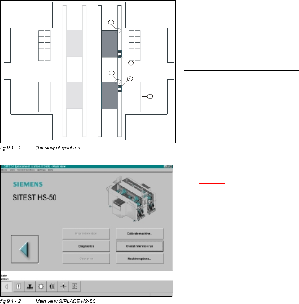
.(<
(1) Calibration tool, placement position 1
(2) Fixed PCB corner
(3) Nozzle changer magazine
(4) Placement area 2
(5) Placement area 2
NOTE
Some calibrations require that you attach
ozzles on the placement heads.
Use nozzles of type .
Make sure that all nozzles have been
attached correctly, otherwise measuring
will lead to incorrect results.
If you need to, place the calibration tool
into the "calibration bag".
(See fig 9.1 - 1
).
Before you place the calibration tool, make
sure that it is clean. Also, be sure that you
insert it into the "calibration bag" with its
print of the fiducial structure on the bottom.
3UHSDUDWLRQVIRU&DOLEUDWLRQ
Å Start SITEST.
Å Under menu item "Main view", click "Overall reference run", to reference all gantry- and head- axes.