00191374-04.pdf - 第169页
Adjustment In structions SIPLACE HS-50 9 Calibrat ion of SIPLACE HS-50 (in cl. SITEST v ersion 501.xx) Softwareversion SR.501.x x Edition 12/00 9.2 Calibration of PCB - Camera 169 &DOL EUDW LRQ RI3&% …
168
9 Calibration of SIPLACE HS-50 (incl. SITEST version 501.xx) Adjustment Instructions SIPLACE HS-50
9.1 Preparations for Calibration Softwareversion SR.501.xx Edition 12/00
5
4
3
2
1
10
9
8
7
6
5
4
3
2
1
10
9
8
7
6
6
7
8
9
10
1
2
3
4
5
6
7
8
9
10
1
2
3
4
5
2
3
4
5
.(<
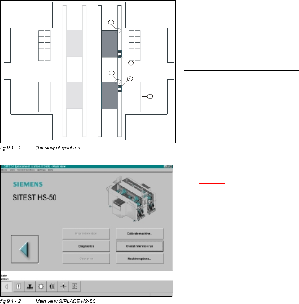
(1) Calibration tool, placement position 1
(2) Fixed PCB corner
(3) Nozzle changer magazine
(4) Placement area 2
(5) Placement area 2
NOTE
Some calibrations require that you attach
ozzles on the placement heads.
Use nozzles of type .
Make sure that all nozzles have been
attached correctly, otherwise measuring
will lead to incorrect results.
If you need to, place the calibration tool
into the "calibration bag".
(See fig 9.1 - 1
).
Before you place the calibration tool, make
sure that it is clean. Also, be sure that you
insert it into the "calibration bag" with its
print of the fiducial structure on the bottom.
3UHSDUDWLRQVIRU&DOLEUDWLRQ
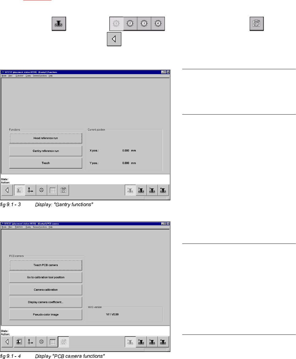
Å Start SITEST.
Å Under menu item "Main view", click "Overall reference run", to reference all gantry- and head- axes.
Adjustment Instructions SIPLACE HS-50 9 Calibration of SIPLACE HS-50 (incl. SITEST version 501.xx)
Softwareversion SR.501.xx Edition 12/00 9.2 Calibration of PCB - Camera
169
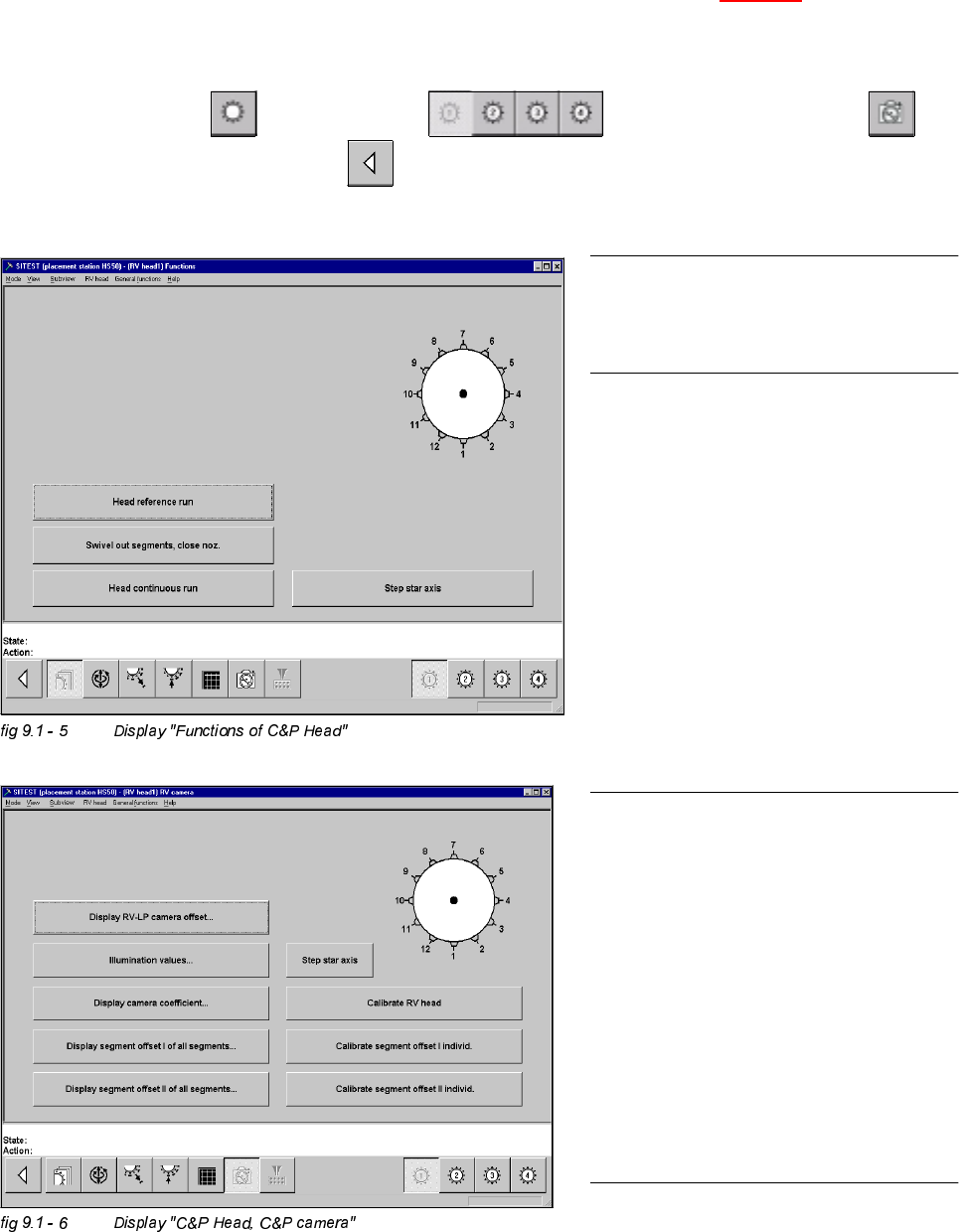
&DOLEUDWLRQRI3&%&DPHUD
Example: PCB - camera, gantry 1
Å Insert the calibration tool into the "calibration bag 1" in placement area 1.
(See
fig 9.1 - 1).
6,7(67
Å Select "Gantry" ==> "Gantry 1" ==> "PCB - camera functions" ==>
"Calibrate camera" ==> "Main view" ==> "Save machine data".
NOTE
Repeat these instructions in order to
calibrate the PCB - cameras of gantries
2, 3 and 4.
NOTE
With the help of the function "Display
camera coefficient", the determined
values can be displayed after you finished
calibration.
The value under "Angle [1 / 100°] must not
exceed 100.
170
9 Calibration of SIPLACE HS-50 (incl. SITEST version 501.xx) Adjustment Instructions SIPLACE HS-50
9.3 Calibration of the Collect & Place Head Softwareversion SR.501.xx Edition 12/00
NOTE
Repeat these instructions in order to
calibrate the C&P Heads 2, 3 and 4.
For the calibration follow these steps:
– Calibration of the PCB - camera
– Calibration of the C&P - camera
– Determination of the segment offsets I
for all 12 segments
– Determination of the segment offsets II
for all 12 segments and the C&P
PCB camera offset, relating to
segment I.
NOTE
With the help of the function "Display
camera coefficient", the determined val-
ues can be displayed after you finished
calibration.
Segment offset I: No deviation > 120 µm
between the individual segments and no
value for a single segment > 450 µm
allowed!
Segment offset II: The value for segment 1
is always 0.
&DOLEUDWLRQRIWKH&ROOHFW3ODFH+HDG
Example: C&P Head 1
Å Insert the calibration tool into the "calibration bag 1" in placement area 1. (See fig 9.1 - 1).
Å Place 12 nozzles, type 956 on the star.
6,7(67
Å Select "C&P Heads" ==> "C&P Head 1" ==> "C&P Head and camera" ==>
"Calibrate camera" ==> "Main view" ==> "Save machine data".