00191374-04.pdf - 第176页
176 9 Calibration of SI PLACE HS-50 (incl. SITES T version 501.xx ) Adjustment Instructions S IPLACE HS-50 9.7 Calibration of Conveyor Width Softwareversion SR.501.xx Edition 12/00 NOTE Usi ng t he fu nc tio ns of …
Adjustment Instructions SIPLACE HS-50 9 Calibration of SIPLACE HS-50 (incl. SITEST version 501.xx)
Softwareversion SR.501.xx Edition 12/00 9.6 Calibration Collect & Place Head Nozzle Changer
175
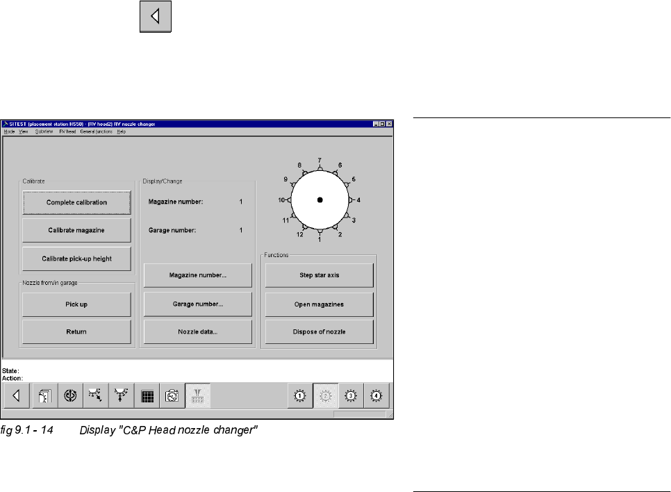
&DOLEUDWLRQRI3LFN8S+HLJKW
Å
Ascertain, that there is a nozzle on the lower segment, and that all garages selected below, are empty.
6,7(67
Å Select "Magazine number..." ==> "Type in magazine number and accept" ==> "Garage number..." ==>
"Type in garage number and accept" ==> "Calibrate pick-up height" ==> "OK".
Å Repeat this procedure for all magazines.
Å Select "Main View" ==> "Save machine data".
NOTE
Each individually determined pick-up
height (z-position) will be displayed in a di-
alogue box, after the calibration.
The z-position of the reject container will
be calculated from the pick-up height
determined for the last magazine.
If you want to test if the calibration was
successful, you should always FIRST
save the determined calibration data
("Main view" ==> "Settings" ==> "Save
machine data"). After saving the data,
return to the display "C&P Head nozzle
changer".
With the help of the functions "Place / Pick-
up" you can test the calibration result.
176
9 Calibration of SIPLACE HS-50 (incl. SITEST version 501.xx) Adjustment Instructions SIPLACE HS-50
9.7 Calibration of Conveyor Width Softwareversion SR.501.xx Edition 12/00
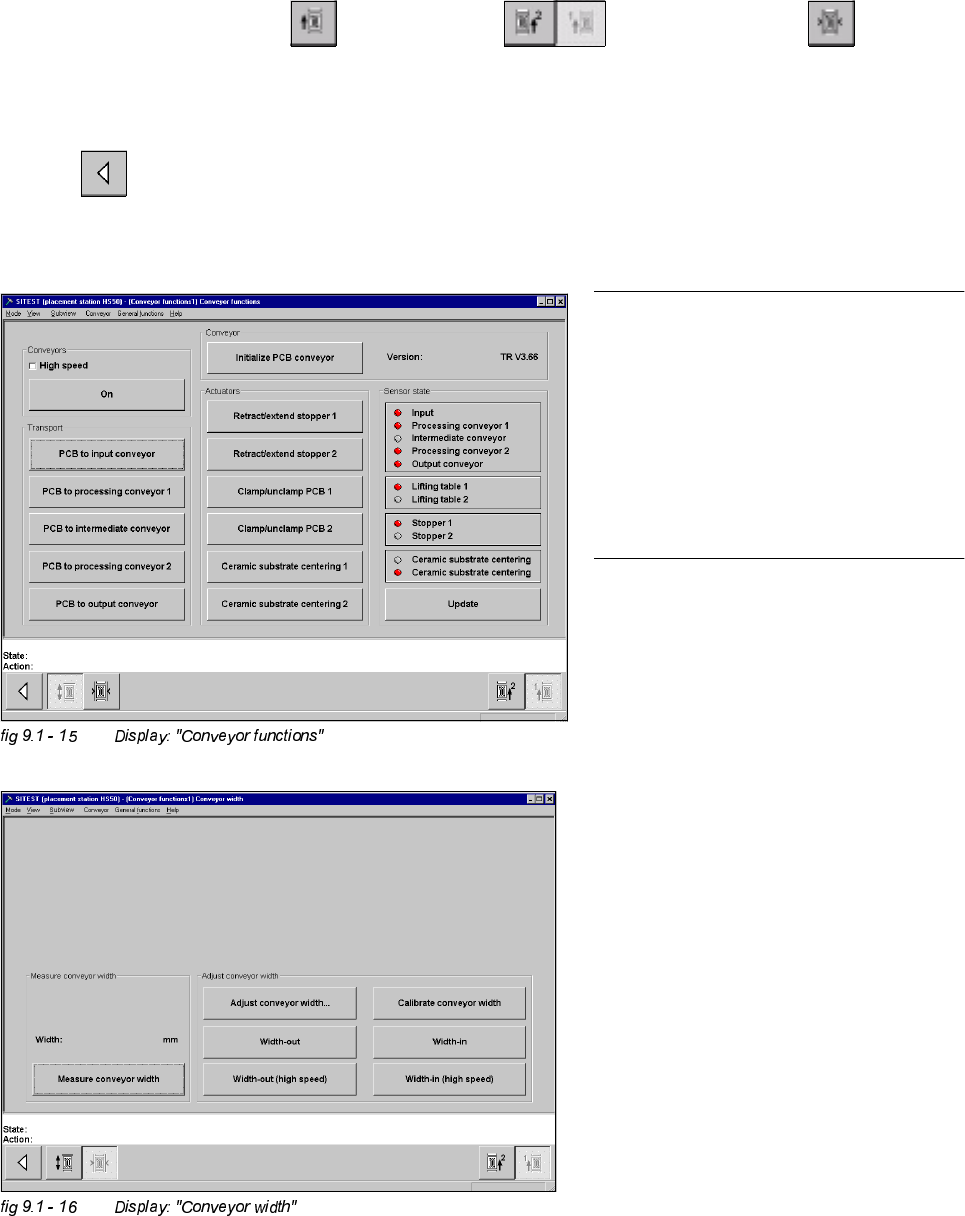
NOTE
Using the functions of the width adjust-
ment, no PCB may be in the conveyor and
the lifting tables must be down.
If the system has a dual conveyor in-
stalled, the conveyor width for conveyor 2
(left - hand conveyor) must get calibrated
as described above.
&DOLEUDWLRQRI&RQYH\RU:LGWK
Example: Conveyor 1 (= right hand conveyor).
6,7(67
Å Select "Placement conveyor" ==> "Conveyor 1" ==> "Conveyor width" ==>
"Calibrate conveyor width" ==> "Insert a PCB with 100 mm of width into conveyor 1" ==> "With the help of
the functions "wider" / "narrower" (in the dialogue box), adjust to the width of the PCB" ==> "OK" ==>"Main
view" ==> "Save machine data". Measuring the Fixed PCB corner
Adjustment Instructions SIPLACE HS-50 9 Calibration of SIPLACE HS-50 (incl. SITEST version 501.xx)
Softwareversion SR.501.xx Edition 12/00 9.8 Measuring the Fixed PCB corner
177
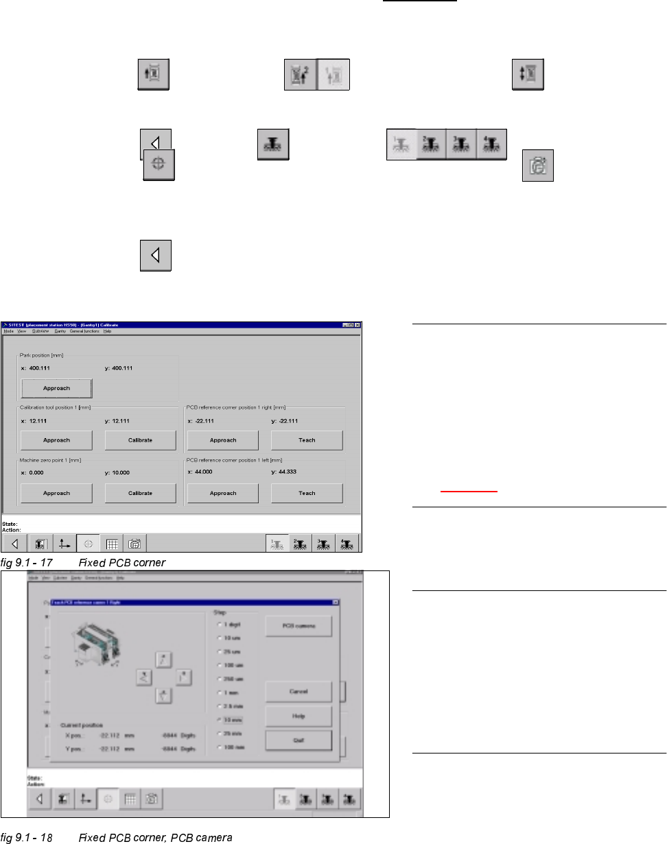
0HDVXULQJWKH)L[HG3&%FRUQHU
Example: Placement area 1 , conveyor of the right hand side (conveyor 1).
Å With the help of the conveyor functions, move a PCB with a light surface into the processing conveyor 1, in
which you wish to measure the position of the fixed PCB corner.
6,7(67
Å Select "Conveyor" ==> "Conveyor 1" ==> "Conveyor functions" .
Å With the help of the conveyor functions, move the PCB into placement area 1.
Å Select "Main view" ==> "Gantry" ==> "Gantry 1" ==>
"Calibrate position" ==> "Teach (field 1, right hand side)" ==> "PCB camera" .
With the help of the cursor buttons, teach the position of the fixed PCB corner.
Å Select ESC accept the position with "End".
Å Select "Main view" ==> "Save machine data".
NOTE
Make sure that the calibration data for the
PCB camera, the segment offset II (C&P -
PCB camera offset) and the machine zero
point have been determined already.
The position of the fixed PCB corners
varies according to conveyor model.
See fig 9.1 - 1.
NOTE
To measure the placement position in
placement area 2, follow the instructions
as detailed above, for gantry 2 as well.
If a dual conveyor is installed, the fixed
PCB corners of the left hand conveyor
(conveyor 2) must be measured as well.