00191374-04.pdf - 第29页
Adjus t ment In str uc tio ns SI PLA CE HS- 50 2 Operational Safety Edition 12/00 2.2 Safety Equipm ent 29 0 DLQ6Z LWFK(0 (5*(1&<67 23%XWWRQV3URWHF WLY H&RYHU 6Z LWF KHV 3RVLWLRQ RI…
2 Operational Safety Adjustment Instructions SIPLACE HS-50
2.2 Safety Equipment Edition 12/00
28
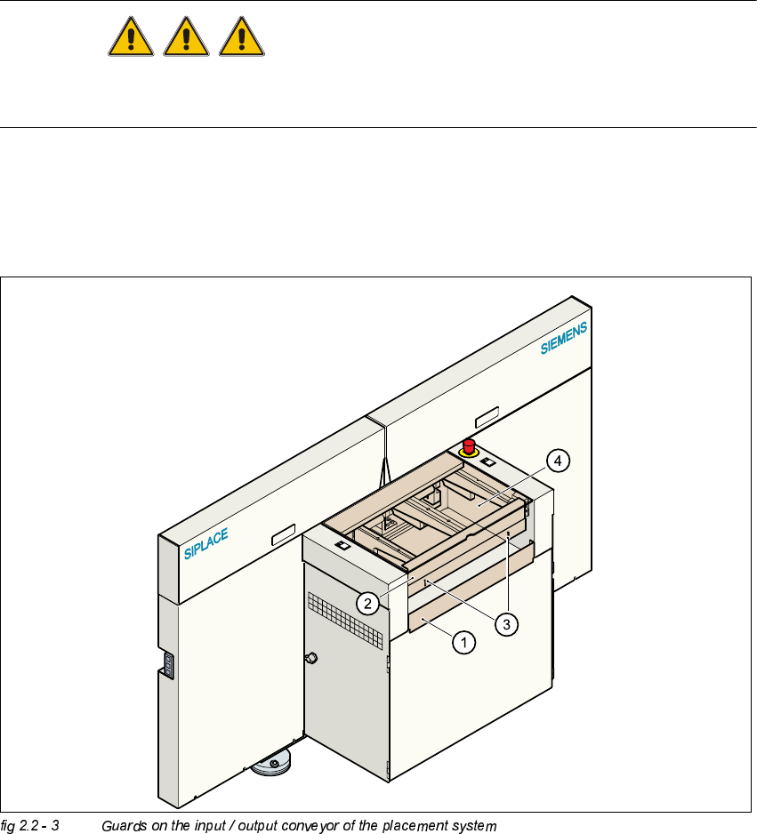
*XDUGRQWKH,QSXW2XWSXW&RQYH\RU
DANGER
The guard must always be set to the height of the PCB to be processed. Ensure that the gap
between the guard and the safety bar is as small as possible.
– Guards are fitted on the input and output belts of the PCB conveyor.
Å The height of the guard must be set using the slots so that the processed PCB can travel
through.
.(<
(1) Safety bar (fixed)
(2) Guards (adjustable)
(3) Slots for adjusting the height
(4) Cover
Adjustment Instructions SIPLACE HS-50 2 Operational Safety
Edition 12/00 2.2 Safety Equipment
29
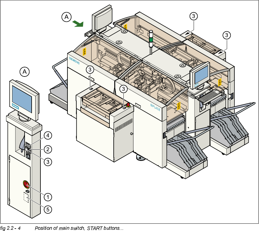
0DLQ6ZLWFK(0(5*(1&<6723%XWWRQV3URWHFWLYH&RYHU6ZLWFKHV
3RVLWLRQRI0DLQ6ZLWFK67$57%XWWRQVRQWKH3ODFHPHQW6\VWHP
(1) Main switch
(2) STOP button (black)
(3) START button (white)
(4) Component counter
(5) Service socket in the power supply unit behind the protective door
2 Operational Safety Adjustment Instructions SIPLACE HS-50
2.2 Safety Equipment Edition 12/00
30
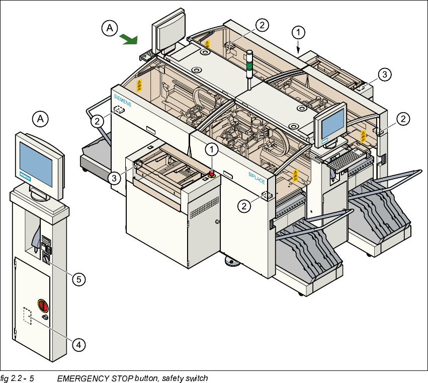
3RVLWLRQRI(0(5*(1&<6723%XWWRQV6DIHW\6ZLWFKHVHWFRQWKH3ODFHPHQW
6\VWHP
.(<
(1) EMERGENCY STOP button
(2) Protective cover switches
(3) Protective cover switches over the PCB conveyors
(4) Protective contactor combination (PCC) in the power supply unit behind the safety doors
(5) Key switch
Key switch open position 0 for normal mode
Key switch closed position I for service purposes