00191374-04.pdf - 第49页
Adjus t ment In str uc tio ns SI PLA CE HS- 50 2 Operational Safety Edition 12/00 2.5 Energy Level after Switching O ff Main Sw itch 49 3ODFHPHQW6\VWHP6Z LWFKHG2IIDW WKH0 D LQ6Z LWFKEXW 6W LOO&RQQHFW…
2 Operational Safety Adjustment Instructions SIPLACE HS-50
2.5 Energy Level after Switching Off Main Switch Edition 12/00
48
.(<
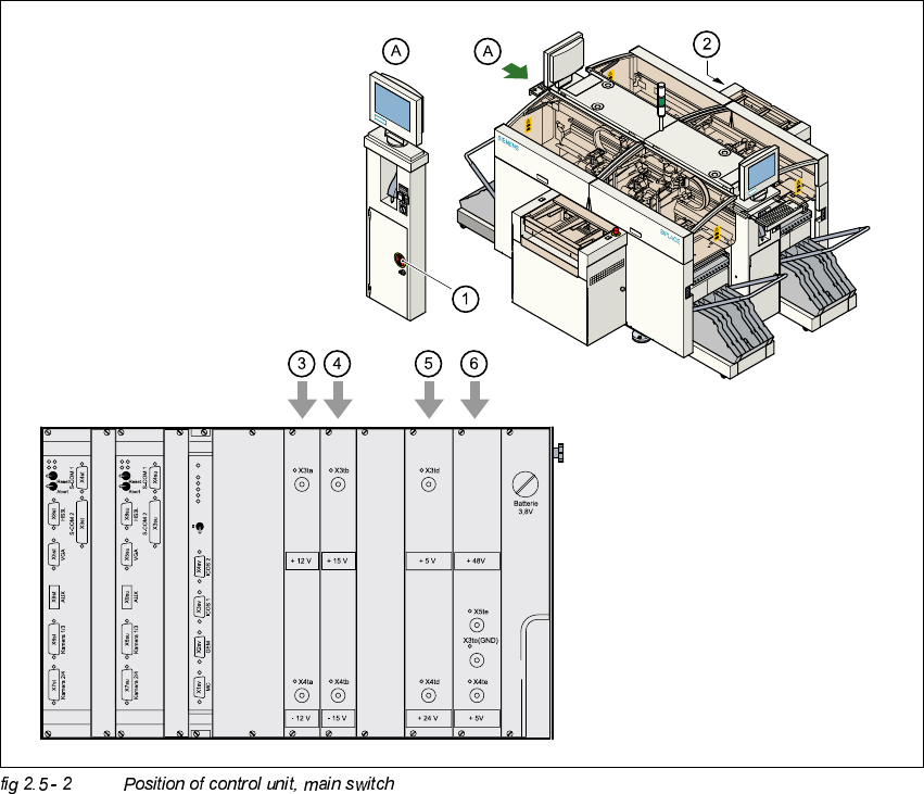
(1) Main switch
(2) Control unit
(3) Power supply unit ± 12 VDC
(4) Power supply unit ± 15 VDC
(5) Power supply unit + 5 VDC/+ 24 VDC
(6) Power supply unit + 5 VDC/+ 50 VDC
Adjustment Instructions SIPLACE HS-50 2 Operational Safety
Edition 12/00 2.5 Energy Level after Switching Off Main Switch
49
3ODFHPHQW6\VWHP6ZLWFKHG2IIDWWKH0DLQ6ZLWFKEXW6WLOO&RQQHFWHG
The following table specifies the voltages of modules when the placement system is switched off
at the main switch, but still remains connected to the mains supply.
DANGER
The following components still carry potentially lethal voltages even if the main switch is switched
off:
– Cable connection terminals 1, 3, and 5 of S1 main switch,
– Z1 mains filter,
– BU1 service socket,
– F1 automatic circuit breaker for the service socket.
– The color of all single wires, which still carry potentially lethal voltages even if the main switch
is switched off is brown.
0RGXOH 9ROWDJH
Mains filter Z1
Terminals L1, L2, L3
3 x 204 V AC
3 x 230 V AC
3 x 380 V AC
3 x 400 V AC
3 x 415 V AC
Service socket BU1
115 V AC
130 V AC
220 V AC
230 V AC
240 V AC
Circuit breaker F1
115 V AC
130 V AC
220 V AC
230 V AC
240 V AC
2 Operational Safety Adjustment Instructions SIPLACE HS-50
2.5 Energy Level after Switching Off Main Switch Edition 12/00
50
3ODFHPHQW6\VWHP6ZLWFKHG2IIDWWKH0DLQ6ZLWFKDQG'LVFRQQHFWHG
The automatic placement system is cut off from all electricity , apart from slight residual voltages
in the servo unit.
&RPSUHVVHG$LU&RQGLWLRQVLQWKH0DFKLQHDIWHU6ZLWFKLQJ2IIWKH0DLQ
6ZLWFK
When the system is switched off at the main switch (item 1 in fig 2.4 - 1) or if the power supply
fails, the electrically controlled main valve Y1 of the compressed air unit closes.
(Item 3 of fig 2.4 - 1
). The pressure will drop to 0 bar within 5 seconds.
Main switch S1
Terminals 1, 3, 5
3 x 204 V AC
3 x 230 V AC
3 x 380 V AC
3 x 400 V AC
3 x 415 V AC
Servo unit (See item 5 of fig 2.5 - 1
)
Test socket X2
Test socket X3
Test socket X4
GND X1
< 10 VDC
< 10 VDC
< 10 VDC
Control unit (See item 3, 4, 5 and 6 of fig 2.5 - 2
)
Test socket + 12 VDC (x3ta)
Test socket - 12 VDC (x4ta)
Test socket + 15 VDC (x3tb)
Test socket -15 VDC (x4tb)
Test socket + 5 VDC (x3td)
Test socket + 24 VDC (x4td)
Test socket + 50 VDC (x5te)
Test socket + 5 VDC (x4te)
GND (x3td)
0 VDC
0 VDC
0 VDC
0 VDC
0 VDC
0 VDC
0 VDC
0 VDC