00191374-04.pdf - 第78页
4 Overview Voltages Adjust ment Inst ruc ti ons SI PLA CE HS- 50 4.6 Measuring Voltages of the Power Supply Unit Edition 12/00 78 246 135 F3 135 246 SZ1 K14 K12 K1 1 13 5 24 6 MS1A MS1 S1 MS5 MS6 MS4 MS3 13 5 2 6 4 2 6…

Adjustment Instructions SIPLACE HS-50 4 Overview Voltages
Edition 12/00 4.6 Measuring Voltages of the Power Supply Unit
77
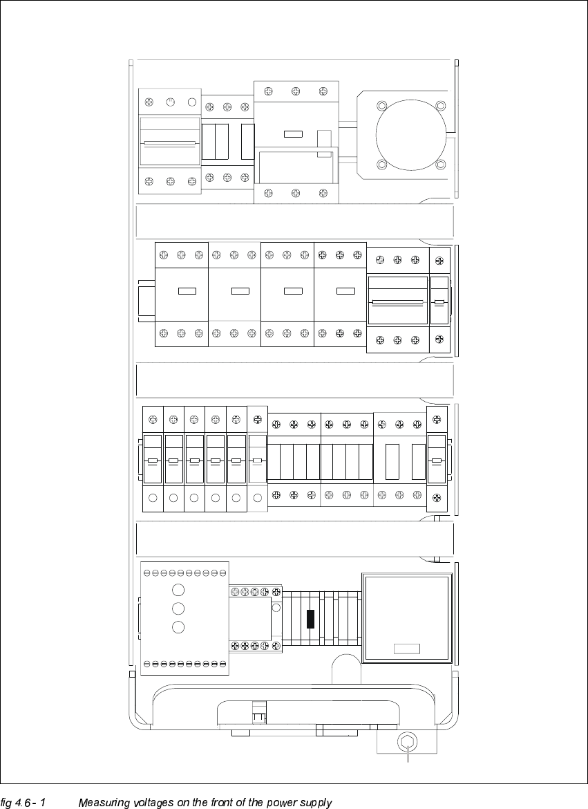
0HDVXULQJ9ROWDJHVRQWKH)URQW6LGHRIWKH3RZHU6XSSO\8QLW
NOTE
Measurements can be taken only while the system is running. This means that the protective
covers as well as the component flaps are closed and the component tables are docked on. The
EMERGENCY STOP button is unlocked and the START button has been pressed.
Operational voltages for the servo amplifier, the lifting tables e.g. would otherwise remain
unswitched.
Module inputs are marked with odd numbers, model outputs with even numbers.
Inputs of fuses (F1 etc.) are always on the bottom side of the module, contactors (SZ1 etc.) and
inputs of motor protective switches (MS1 ...) are always on the top.
4 Overview Voltages Adjustment Instructions SIPLACE HS-50
4.6 Measuring Voltages of the Power Supply Unit Edition 12/00
78
246
135
F3
135
246
SZ1
K14
K12
K11
135
246
MS1A
MS1
S1
MS5 MS6MS4MS3
135
2 64 2 64
1 53 31 5
42 6 624
5
13
F4
426
3
1
5
F10F9F8F7F6F5
111111
222 222
F1
2
1
SZ2 SZ3
SZ23
246
1351
3
5
2
4
6
2
4
6
1
3
5
K232
K234
K34
K33
K32
K31
K21
K22
K23
K24
SSK
1 375
4268
A1+
A2-
SZ4
X1
VUWW
PE
PE
N
BU1
M8
F11
2
1
54 6614 24 4434X4 X6L-
13L+ X3X1 X5 533323 43 65
Netz
Power
Channel 1
Kanal 1
Channel 2
Kanal 2

Adjustment Instructions SIPLACE HS-50 4 Overview Voltages
Edition 12/00 4.6 Measuring Voltages of the Power Supply Unit
79
0RGXOH 'HVLJQDWLRQ &ODPSV 9ROWDJHV
X1
connecting terminal panel
power supply
U, V, W
3 x 204 VAC / 3 x 380 VAC /
3 x 400 VAC / 3 x 415 VAC
BU1
service socket 115 VAC / 220 VAC / 230VAC / 240 VAC
S1
main switch
1, 3, 5 u.
2, 4, 6
3 x 204 VAC / 3 x 380 VAC /
3 x 400 VAC / 3 x 415 VAC
MS1
motor protective switch
1, 3, 5 u.
2, 4, 6
3 x 204 VAC / 3 x 380 VAC /
3 x 400 VAC / 3 x 415 VAC
SZ1
main contactor
1, 3, 5 u.
2, 4, 6
3 x 204 VAC / 3 x 380 VAC
3 x 400 VAC / 3 x 415 VAC
MS3
MS4
MS5
MS6
motor protective switch
PCB conveyor 1
motor protective switch
PCB conveyor 2 (option)
1, 3, 5 u.
2, 4, 6
1, 3, 5 u.
2, 4, 6
3 x 230 VAC
3 x 230 VAC
3 x 230 VAC
3 x 230 VAC
SZ2
contactor
1, 3, 5
2, 4, 6
3 x 140 VAC
3 x 140 VAC
SZ3
contactor
1, 3, 5
2, 4, 6
3 x 140 VAC
3 x 140 VAC
SZ23
contactor
1, 3, 5
2, 4, 6
3 x 140 VAC
3 x 140 VAC
SZ4
contactor
A1 (+) - A2 (-)
1, 2
3, 4
5, 6
24 VDC
24 VDC against ground
24 VDC against ground
24 VDC against ground
SSK
protective contactor
combination
L+, X3, X5 24 VDC against ground
F1
fuse
service socket
1, 2
115 VAC / 220 VAC
230 VAC / 240 VAC
against N on the connecting terminal panel 1
F3
fuse
board net
1, 3, 5
2, 4, 6
3 x 230 VAC
F4
fuse
x- / y- axis
1, 3, 5
2, 4, 6
3 x 140 VAC
F5
fuse
star - axis
1, 2 100 VDC against minus of rectifier V3.
F6
fuse
z- and dp - axis
1, 2 30 VDC against minus of rectifier of V4.