00191374-04.pdf - 第94页
5 Single and Dual PCB Conv eyor Adjustment Instructions S IPLACE HS-50 5.5 Adjustment of Transport Parallelism Edition 12/00 94 $G MXVWP HQW RI7 UDQVSRUW 3DUDOOHOL VP .(< (1) Reachabl e posi tion for adjust…
Adjustment Instructions SIPLACE HS-50 5 Single and Dual PCB Conveyor
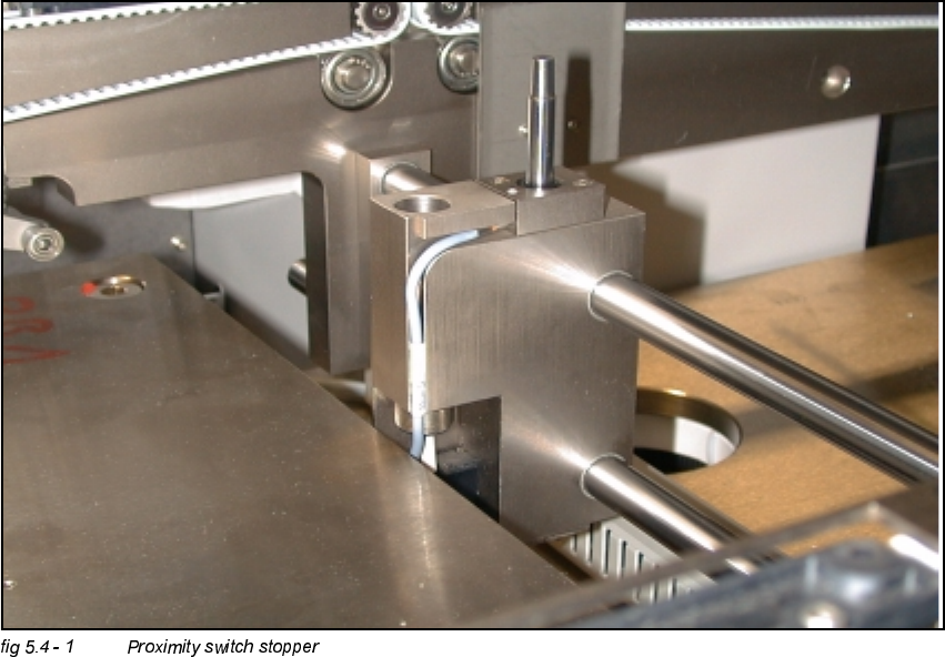
Edition 12/00 5.4 Adjustment of the Proximity Switches PCB Stopper
93
$GMXVWPHQWRIWKH3UR[LPLW\6ZLWFKHV3&%6WRS
SHU
Å Utilize the menu for the extraction of the PCB stopper.
6,7(67
Å Select "Transport functions" ==> "PCB conveyor 1 or 2" ==> "Stopper 1 (2)
retract / extract".
Å Carefully, move the proximity switch until contact is reached.
Å Pull back the proximity switch until a small gap of approximately 0.2 mm is reached, while the
contact must not get interrupted.
5 Single and Dual PCB Conveyor Adjustment Instructions SIPLACE HS-50
5.5 Adjustment of Transport Parallelism Edition 12/00
94
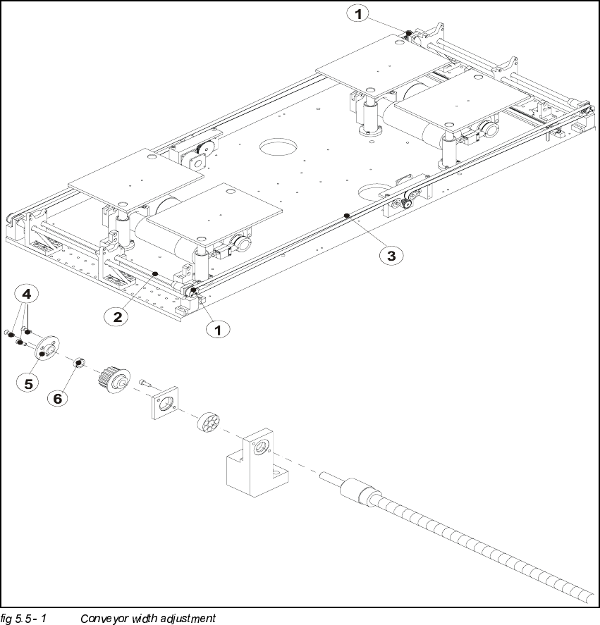
$GMXVWPHQWRI7UDQVSRUW3DUDOOHOLVP
.(<
(1) Reachable position for adjustment
(2) Spindle
(3) Toothed belt width adjustment
(4) Fixing screw
(5) Fixing plate
(6) Clamping piece

Adjustment Instructions SIPLACE HS-50 5 Single and Dual PCB Conveyor
Edition 12/00 5.5 Adjustment of Transport Parallelism
95
NOTE
Due to limited accessibility, adjustments as described above can only be performed from one side
each.
Å Move the conveyor to 100 mm on one side.
Å Loosen the three screws and take out the disk of the pressure flange.
NOTE
Watch out for the annular spring; it might fall.
Å Hold on to the untightened spindle.
Å With the help of the spindle, move the conveyor on the opposite side, until you reach a distance
of 100 mm there as well.
Å Check, if the measures of the conveyor are by now identical on both sides.
Å In order to fix the spindle follow the same procedure, just the opposite way.
NOTE
Make sure that during the fixing of the spindle, the conveyor remains unmoved.
6,7(67
Å Use the conveyor functions, in order to test the conveyor width adjustment, .