00198243-01_AI_BulkFeederX_XS-SX_DE+EN.pdf - 第114页
4 Retrofit kit for X-Series S 4.2 Preparatory steps 114 Assembly Instructions / Montageanleitung SIPLACE BulkFeeder X Retrofit Kit for SX Series and X Series S 07/2017 ► The retrofitted computer is now ready. There are f…
4 Retrofit kit for X-Series S
4.2 Preparatory steps
Assembly Instructions / Montageanleitung SIPLACE BulkFeeder X Retrofit Kit for SX Series and X Series S 07/2017 113
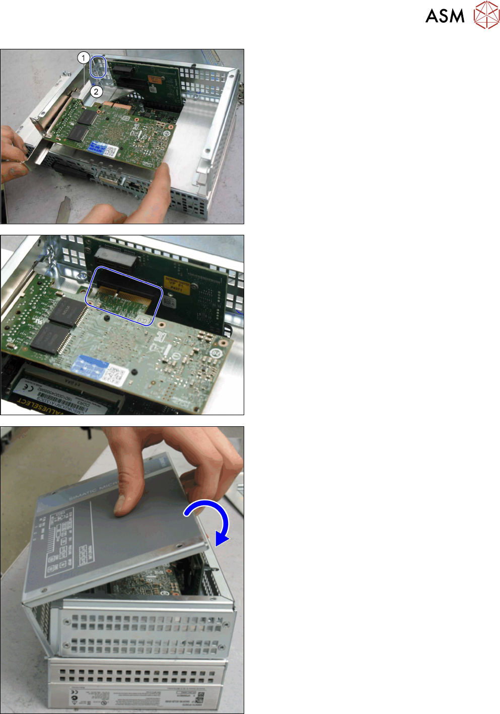
► Insert the GigE card in place of the protective
cover. Make sure that the "nib" on the guide rail
(1) correctly engages at the point where it is in-
serted (2).
► The card has a press-fit connection at the head
end. When inserting the GigE card, make sure
that this press-fit connection engages correctly
with the point opposite into which it is inserted.
► Use the fastening screw previously removed to
screw the GigE card tight.
► Close the computer: place the housing cover
back onto the hinges at the side.
► Swing the cover closed, until it engages in the
computer frame.
► Use the screws to fasten the cover.
4 Retrofit kit for X-Series S
4.2 Preparatory steps
114 Assembly Instructions / Montageanleitung SIPLACE BulkFeeder X Retrofit Kit for SX Series and X Series S 07/2017
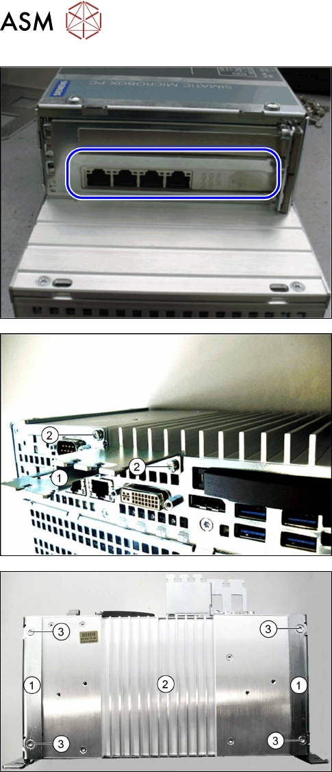
► The retrofitted computer is now ready. There are
four LAN ports for connection of the BulkFeeder
X LAN cable.
► Connection of the cable is described in the cable
instructions and in section 4.6 "Connecting the
cable" [}128].
► At the side, fit the Profibus (1) for strain relief and
the cable guidance with fastening screws (2).
► Position the two book holders (1) onto the Bulk-
Feeder X computer (2) and fasten these with the
screws provided (3) to the rear side. This allows
you to fit the BulkFeeder X computer later into
the additional holder, next to the pneumatic unit
at location 4.
4 Retrofit kit for X-Series S
4.3 Fitting the BulkFeeder X computer
Assembly Instructions / Montageanleitung SIPLACE BulkFeeder X Retrofit Kit for SX Series and X Series S 07/2017 115
4.3 Fitting the BulkFeeder X computer
NOTICE
Number of persons for assembly
If possible, 2 people should be available for the assembly.
The BulkFeeder X computer is fitted behind the corner cover at location 4, under the pneumatic
unit.
4.3.1 Dismantling the lower side cover
To fit the BulkFeeder X computer at location 4, you need to remove the side cover. To do so, pro-
ceed as follows:
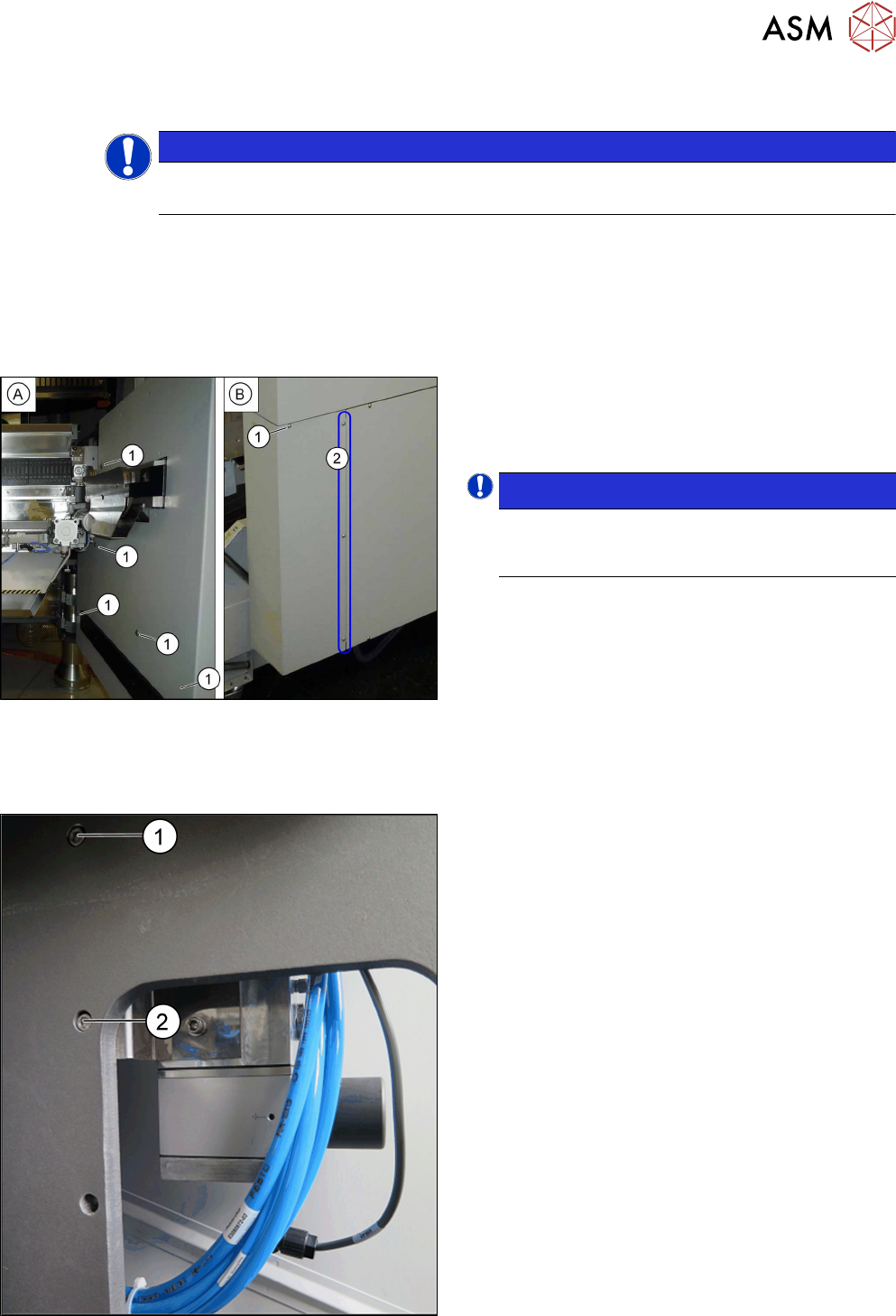
► Loosen the six screws(1) fastening the inside(A)
and outside(B) of the side cover and remove the
side cover. While unscrewing, always hold on to
the side cover, to prevent it falling off.
NOTICE!
The three fastening screws (2) on the outer
side are just loosened. The side cover can be
pulled out here.
.
4.3.2 Fitting the Bulkfeeder X computer
To fit the BulkFeeder X computer behind the corner cover at location 4, you need to fit an additional
holder next to the pneumatic unit. To do so, proceed as follows:
► Remove the top screw (1) for the pneumatic unit.
► Insert the longer screw M6x20 through the open-
ing. Rotate is about twice so that it holds the unit.
► Remove the bottom screw (2) for the pneumatic
unit. The pneumatic unit can now be moved.