00196602-05_SM_SIPLACE_X-Feeder_EN.pdf - 第31页
6 Repairing the X Feeder modules 6.4 Tape Drive Service Manual SIPLACE X-Feeder 4 - 88 mm 11/2017 31 ► (1) Fasten the pickup window to the left side of the feeder module. Use the bearing screw X16-88 , item no. 03021264-…
6 Repairing the X Feeder modules
6.4 Tape Drive
30 Service Manual SIPLACE X-Feeder 4 - 88 mm 11/2017
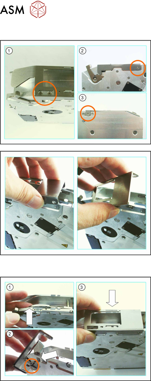
6.4.1.3 Removing the Pickup Window (16 - 88 mm)
► (1) Loosen the two marked screws which fasten
the spring holder to the pickup window.
► Remove the two screws, the tape spring and the
spring holder out of the pickup window.
► (2) Loosen the marked screw on the left-hand
side of the feeder module.
► (3) Loosen the marked screw on the right-hand
side of the feeder module.
► First lift the pickup window at the back.
► Tilt the pickup window, incline it to the left and lift
it off the feeder module.
6.4.1.4 Fitting the Pickup Window (16 - 88 mm)
► (1) Lift the reject device and hold with one finger.
► (2) Hold the pickup window inclined and hook
from the left into the opening in the feeder mod-
ule.
► (3) Swivel the pickup window so that the back
part is over the feeder module and hold the
pickup window in a horizontal position.
Make sure that the pickup window also projects
beyond the feeder module on the right outer side.
► Lower the pickup window over the snap tabs on
the feeder module.
The pickup window should be fitted loosely on
the feeder module.
6 Repairing the X Feeder modules
6.4 Tape Drive
Service Manual SIPLACE X-Feeder 4 - 88 mm 11/2017 31
► (1) Fasten the pickup window to the left side of
the feeder module.
Use the bearing screw X16-88, item no.
03021264-xx for this.
► (2) Fix the pickup window to the right-hand side
of the feeder module.
When using feeder modules with widths of 16,
32–56 and 88mm, use the bearing screw
X16-88, item no. 03021264-xx
For feeder modules with widths of 24mm and
72mm, use the shorter bearing screw X24x72,
item no. 03012350-xx.. You will need to place a
washer underneath when fitting this screw (bush-
ing), item no. 03007433-xx.
► Insert the tape spring into the hole.
► Hold the spring holder so that the straight side is
on the outside.
► Position the spring holder with the recess on the
tape spring.
► Initially fix the spring holder loosely with a screw.
Do not tighten the screw yet, to avoid distorting
the spring holder and screws.
► Fix the spring holder with the second screw.
► Now tighten the first screw.
6.4.2 Splice Sensor
Required spare parts
Example:splice sensor 8-12mm (left), 16-88mm(right)
Feeder module Item no. Designation
8–12mm 03060695-Sxx Splice sensor B3+ / X8-X12
16–88mm 03038133-Sxx Splice sensor S5
Required tools
●
TORX screwdriver size T8
●
Phillips screwdriver
6 Repairing the X Feeder modules
6.4 Tape Drive
32 Service Manual SIPLACE X-Feeder 4 - 88 mm 11/2017
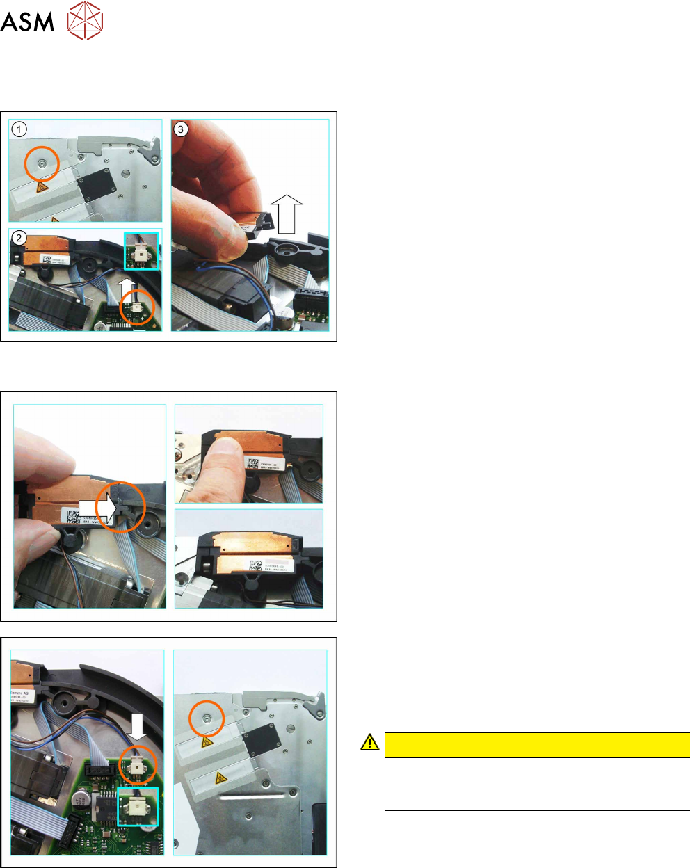
6.4.2.1 Removing the Splice Sensor (8 - 12 mm)
► Remove the left side cover (see 6.3.1 "Removing the Left Side Cover" [}23]).
► (1) Loosen the screw on the right side cover, as
marked in the diagram.
► (2) Carefully push the connector up and out of
the connection marked in the diagram, using a
small slotted screwdriver or similar tool.
Push the connector and do NOT pull on the
cable.
► Lift the splice sensor up and out of the holding
device.
6.4.2.2 Fitting the Splice Sensor (8 - 12 mm)
► Push the splice sensor from the left, with the
snap tab, as far as the stop in the holding device
on the tape duct.
► Press the splice sensor on the left side, down into
the recess next to the tape drive.
► Make sure that the smooth side of the connector
is at the top.
► Carefully insert the connector as far as the stop,
into the connection on the board, as marked in
the diagram.
CAUTION!
Do not push the connector with force into the
connection, otherwise individual pins may break
off or be distorted.
.
► Fix the splice sensor to the right side cover with
the mushroom head cutting screw (T2.5x6mm).
► Fit the left side cover into place (see section 6.3.2 "Fitting the Left Side Cover" [}24]).
► Fit the rear slide bearing (see 6.2.2 "Fitting the Rear Sliding Guide" [}22]).