00196602-05_SM_SIPLACE_X-Feeder_EN.pdf - 第38页
6 Repairing the X Feeder modules 6.5 Foil Disposal 38 Service Manual SIPLACE X-Feeder 4 - 88 mm 11/2017 Modules with upgrade kit: Feeder modules which contain an upgrade kit (marked with a label on the left), can have th…
6 Repairing the X Feeder modules
6.5 Foil Disposal
Service Manual SIPLACE X-Feeder 4 - 88 mm 11/2017 37
6.5 Foil Disposal
6.5.1 Foil Disposal Drive Assembly
NOTICE
Checking the firmware version
After replacing the foil disposal drive, you need to check the firmware version for the feeder
module with the X-Feeder Testbox.
The firmware needs to be updated if the firmware supplied on a USB stick with the X-
Feeder Test Station has a higher version state than the firmware in the feeder module.
For a description of how to update the firmware, refer to the Job Guide "X Feeder Test Sta-
tion", item no. 00196352-xx.
NOTICE
Using the supplied USB stick
Use the USB stick supplied with the X-Feeder Test Station to check and update the firm-
ware.
Correct functionality can not be guaranteed with other USB sticks which, for example, simu-
late a drive or have high volume memory.
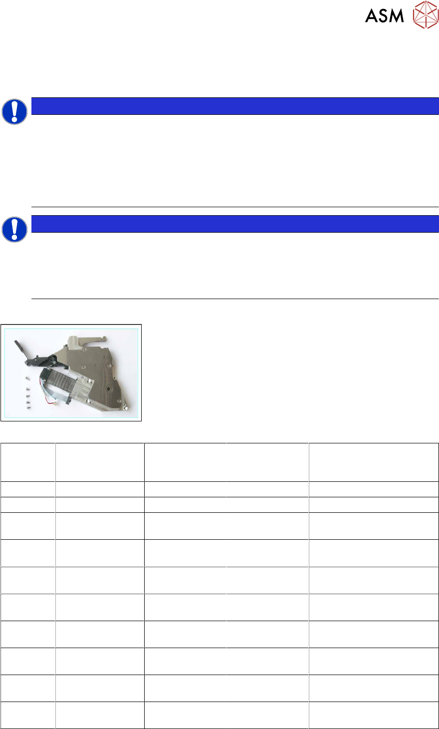
Required spare parts
Example: foil disposal drive 8mm
Feeder
module
Item no. Module
Version <= -06
Item no. Module
with upgrade
kit
Item no. Module
Version >= -07
Designation
4 mm 03087962-xx 03087962-xx 03087962-xx Foil disposal assembly, X4
8 mm 03042325-xx 03042325-xx 03042325-xx Foil disposal assembly, /X8
12 mm 03042419-xx 03042419-xx 03042419-xx Foil disposal assembly, /
X12
16 mm 03042357-xx 03117064-xx
03117048-xx
03117064-xx Foil disposal assembly, /
X16
24 mm 03041992-xx 03117102-xx
03117050-xx
03117102-xx Foil disposal assembly, /
X24
32 mm 03042455-xx 03117106-xx
03117051-xx
03117106-xx Foil disposal assembly, /
X32
44 mm 03042501-xx 03117108-xx
03117053-xx
03117108-xx Foil disposal assembly, /
X44
56 mm 03043390-xx 03117174-xx
03117054-xx
03117174-xx Foil disposal assembly, /
X56
72 mm 03043408-xx 03117340-xx
03117061-xx
03117340-xx Foil disposal assembly, /
X72
88 mm 03042235-xx 03117356-xx
03117062-xx
03117356-xx Foil disposal assembly, /
X88
6 Repairing the X Feeder modules
6.5 Foil Disposal
38 Service Manual SIPLACE X-Feeder 4 - 88 mm 11/2017
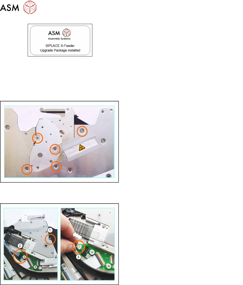
Modules with upgrade kit:
Feeder modules which contain an upgrade kit (marked with a label
on the left), can have the module version -07 foil disposal assem-
bly fitted as a spare part (item no.).
You must also replace the stuffing gear for the rocker opposite with
a module -07 version.
Required tools
●
Phillips screwdriver
●
TORX screwdriver size T8
6.5.1.1 Removing the Foil Disposal Drive (4 - 12 mm)
► First remove the rocker (see 6.6.2.1 "Removing
the Rocker (4 - 88 mm)" [}69]).
► Now carefully place the feeder module down on
its left side.
► Remove the screws marked in the diagram.
► Carefully place the feeder module on its right side.
► Remove the left side cover (see 6.3.1 "Removing the Left Side Cover" [}23]).
► (1) Loosen the screw marked in the diagram.
► (2) Pull the connector marked in the diagram out
of its connection.
To loosen the connector, move it carefully from
side to side.
► (3) Pull the other connector marked in the dia-
gram out of its connection.
Pull on the connector and NOT on the cable.
6 Repairing the X Feeder modules
6.5 Foil Disposal
Service Manual SIPLACE X-Feeder 4 - 88 mm 11/2017 39
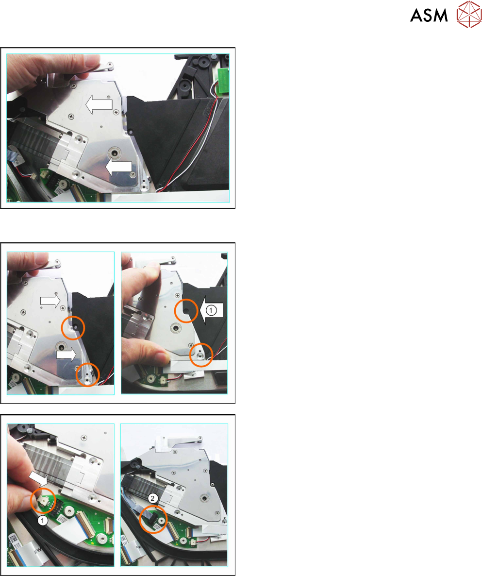
► Lift the right side of the feeder module a little.
► Lift the foil disposal drive slightly and pull it to the
left (keep it straight) and out of the feeder.
6.5.1.2 Fitting the Foil Disposal Drive (4 - 12 mm)
► Lift the right side of the feeder module a little.
► Push the foil disposal drive into the feeder mod-
ule from the left (keep it straight), as far as the
stop.
Make sure that the foil disposal drive lies against
the feeder module at the circular points marked in
the diagram.
► (1) Fix the foil disposal drive into place with the
screw, at the position marked in the diagram.
► Make sure that the smooth side of the connector
is at the top.
► (1) Carefully push the connector as far as the
end stop into the marked connection on the
board.
Attention:
Do not push the connector with force into the connec-
tion, otherwise individual pins may break off or be dis-
torted.
► (2) Push the other connector as far as the end
stop, into the marked connection on the board.
► Fit the left side cover into place (see section 6.3.2 "Fitting the Left Side Cover" [}24]).
► Fit the rocker (see 6.6.2.2 "Fitting the Rocker (4 - 88 mm)" [}70]).
► Carefully place the feeder module down on its left side.