00196602-05_SM_SIPLACE_X-Feeder_EN.pdf - 第75页
6 Repairing the X Feeder modules 6.7 Operating Panel Assembly Service Manual SIPLACE X-Feeder 4 - 88 mm 11/2017 75 ► (1) Carefully swing the lock on the flat ribbon cable connection up to the left and release the flat ri…
6 Repairing the X Feeder modules
6.7 Operating Panel Assembly
74 Service Manual SIPLACE X-Feeder 4 - 88 mm 11/2017
Required tools
●
Flat bladed (slotted) screwdriver
●
Split pin punch size 1.4
Procedure for rocker bearing shaft
When replacing the rocker bearing shaft, follow the instructions in 6.6.2 "Rocker Assembly" [}68].
Instead of replacing the rocker, replace the old bearing shaft with a new one.
Procedure for plain tamp wheel bearing shaft
To replace the bearing shaft of the plain tamp wheel, proceed as described in the 6.6.3 "Tamp
Wheel for Rocker" [}71] below. However, instead of the tamp wheel, just replace the old bearing
shaft with a new one.
NOTICE
Thread may be damaged
Carefully fasten the bearing shaft, not too firmly, so that the thread is not damaged.
6.7 Operating Panel Assembly
The operating panel and the removal handle are always replaced together.
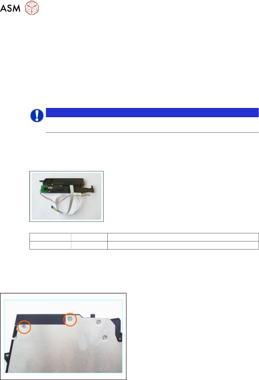
Required spare parts
Example: operating panel 8-88mm
Feeder module Item no. Designation
8–88mm 03009198-Sxx Operating control assembly, with cable / X series
Required tools
●
TORX screwdriver size T8
●
Phillips screwdriver
6.7.1 Removing the Operating Panel (4+8 mm)
► Carefully place the feeder module down on its left
side.
► Loosen the 2 screws marked in the diagram.
► Now carefully place the feeder module down on
its right-hand side.
► Remove the left side cover (see 6.3.1 "Removing
the Left Side Cover" [}23]).
6 Repairing the X Feeder modules
6.7 Operating Panel Assembly
Service Manual SIPLACE X-Feeder 4 - 88 mm 11/2017 75
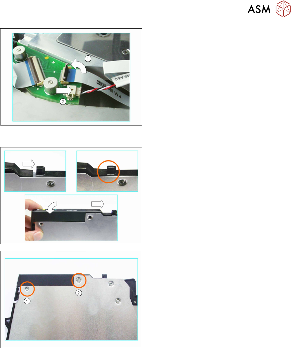
► (1) Carefully swing the lock on the flat ribbon
cable connection up to the left and release the
flat ribbon cable.
Make sure that the lock is not pushed too far
back. The lock could break off if you do this.
► (2) Carefully pull the connector marked in the dia-
gram out of its connection in the direction of the
arrow. Pull on the connector and NOT on the
cable.
6.7.2 Fitting the Operating Panel (4+8mm)
► Push the operating panel from the left, as far as
possible against the track ruler tabs.
► Lower the back part of the operating panel down
to the stop.
Make sure that you can see the holes for the
screws through the holes in the side cover.
► Carefully place the feeder module down on its left
side.
► Fix the operating panel with the 2 screws marked
in the diagram.
(1) countersunk screw (2.5x6 mm)
(2) mushroom head cutting screw (2.5x7.5mm)
► Carefully place the feeder module on its right
side.
6 Repairing the X Feeder modules
6.7 Operating Panel Assembly
76 Service Manual SIPLACE X-Feeder 4 - 88 mm 11/2017
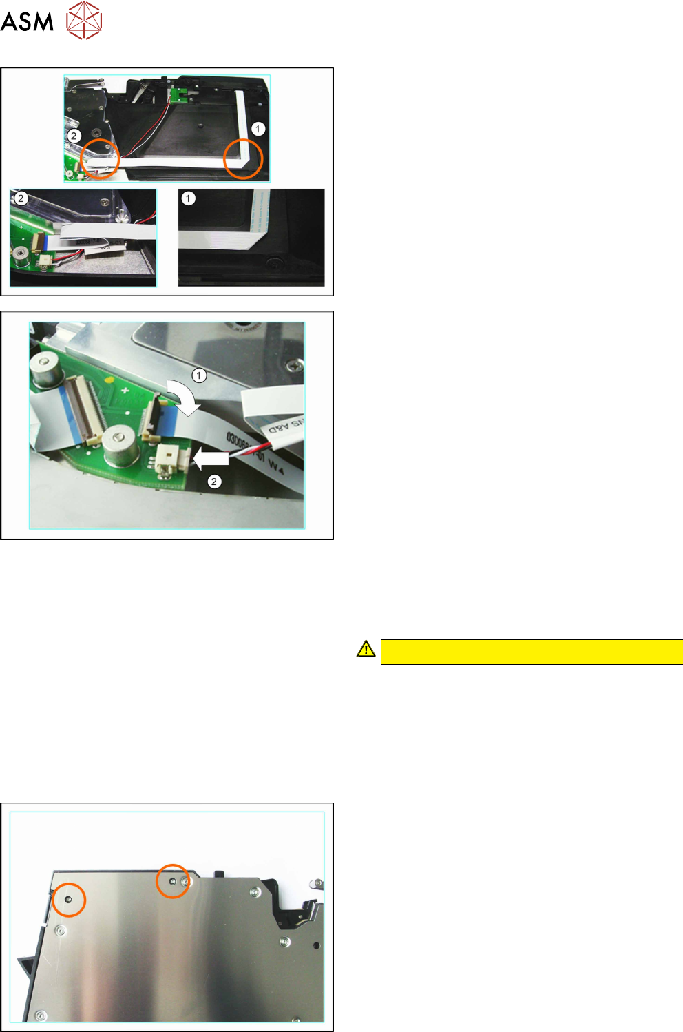
► Insert the foil disposal drive, together with the foil
container, into the feeder module.
Run the cable as marked in the diagram:
► (1) Run the flat ribbon cable vertically downwards
and carefully fold it to the left.
► (2) Carefully fold the flat ribbon cable as marked
in the diagram.
Make sure that the blue surface at the end of the
cable is at the top.
► Thread the other cable under the flat ribbon
cable, to the second connection.
► (1) Insert the flat ribbon cable into the connection,
as far as the stop.
Make sure that the blue surface at the end of the
cable is at the top and that the flat ribbon cable
lies straight in the connection.
► Swing the lock on the connection down onto the
flat ribbon cable.
Make sure that the flat ribbon cable is fitted firmly
in the connection. Tug gently on the cable to
check.
► Check again whether the flat ribbon cable is fitted
straight in the connection.
If necessary, open the lock and correct the posi-
tion of the cable before closing the lock again.
► (2) Insert the connector carefully in the direction
of the arrow and as far as the stop, into the con-
nection shown.
Make sure that the smooth side of the connector
is at the top.
CAUTION!
Do not push the connector with force into the
connection, otherwise individual pins may
break off or be distorted.
.
► Fit the left side cover into place (see 6.3.2 "Fitting
the Left Side Cover" [}24]).
6.7.3 Removing the Operating Panel (12 mm)
► Carefully place the feeder module down on its left
side.
► Loosen the 2 screws marked in the diagram.
► Now carefully place the feeder module down on
its right-hand side.
► Remove the left side cover (see 6.3.1 "Removing
the Left Side Cover" [}23]).