00196602-05_SM_SIPLACE_X-Feeder_EN.pdf - 第79页
6 Repairing the X Feeder modules 6.7 Operating Panel Assembly Service Manual SIPLACE X-Feeder 4 - 88 mm 11/2017 79 ► (1) Push the front part of the control panel as far as the stop into the slit in the foil container fra…
6 Repairing the X Feeder modules
6.7 Operating Panel Assembly
78 Service Manual SIPLACE X-Feeder 4 - 88 mm 11/2017
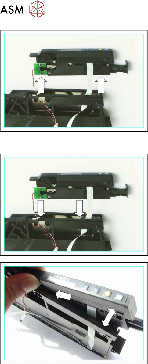
► Pull both cables out of the foil container frame.
6.7.4 Fitting the Operating Panel (12 mm)
► Thread the cable into the foil container frame as
marked in the diagram.
The control panel gets caught slightly on the foil con-
tainer frame during insertion.
► Carefully spread the foil container frame apart.
► Carefully jog the control panel into the foil con-
tainer frame.
6 Repairing the X Feeder modules
6.7 Operating Panel Assembly
Service Manual SIPLACE X-Feeder 4 - 88 mm 11/2017 79
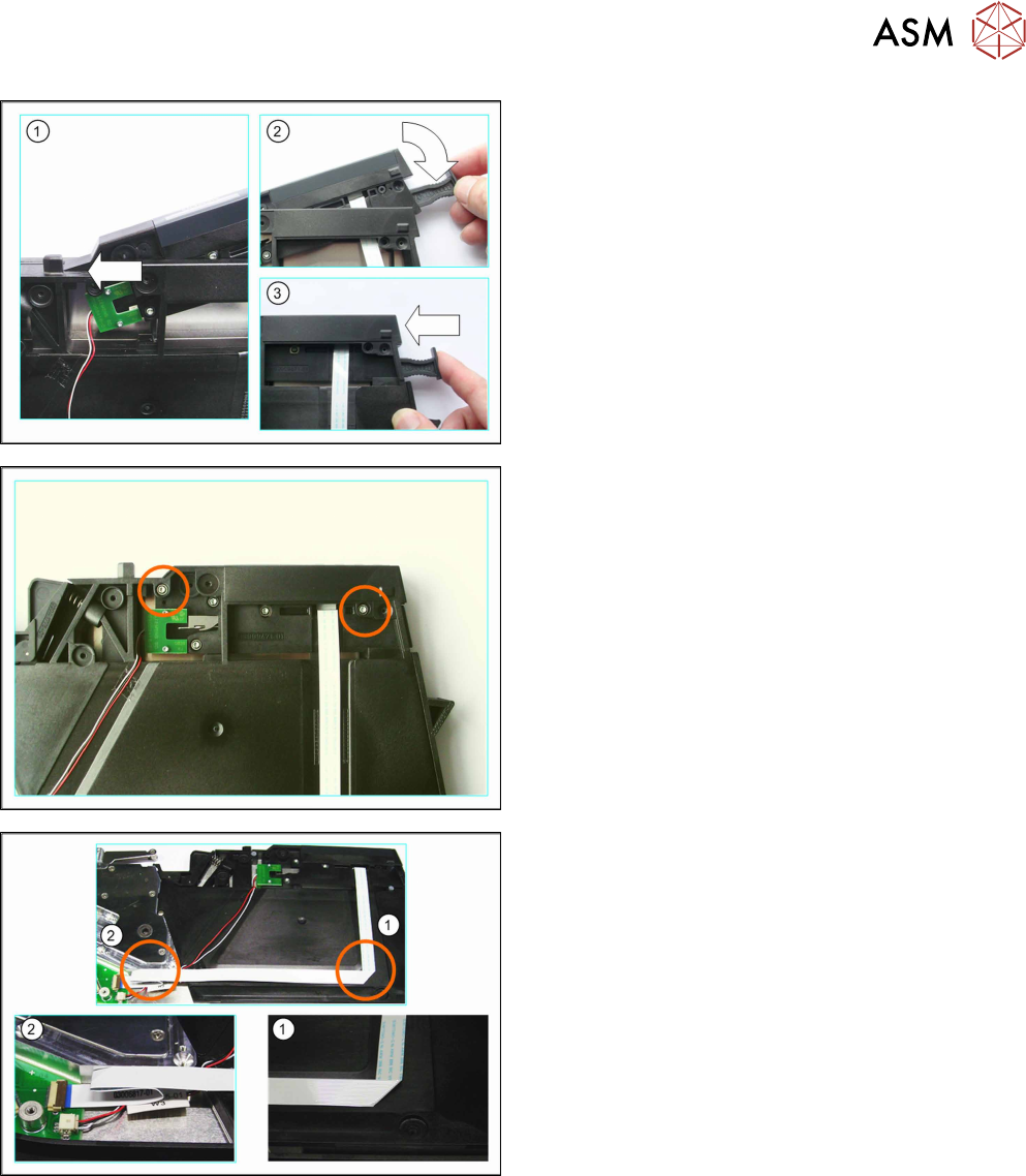
► (1) Push the front part of the control panel as far
as the stop into the slit in the foil container frame.
► (2) Pull the control panel towards the foil con-
tainer.
► (3) Press the release handle into the control
panel.
► Fix the control panel with the self-cutting Torx
screws marked in the diagram.
Run the cable as shown in the example diagram (8
mm feeder module).
► (1) Run the flat ribbon cable vertically downwards
and carefully fold it to the left.
► (2) Carefully fold the flat ribbon cable as marked
in the diagram.
Make sure that the blue surface at the end of the
cable is at the top.
► Thread the other cable under the flat ribbon
cable, to the second connection.

6 Repairing the X Feeder modules
6.7 Operating Panel Assembly
80 Service Manual SIPLACE X-Feeder 4 - 88 mm 11/2017
► (1) Insert the flat ribbon cable into the connection,
as far as the stop.
Make sure that the blue surface at the end of the
cable is at the top and that the flat ribbon cable
lies straight in the connection.
► Swing the lock on the connection down onto the
flat ribbon cable.
Make sure that the flat ribbon cable is fitted firmly
in the connection. Tug gently on the cable to
check.
► Check again whether the flat ribbon cable is fitted
straight in the connection.
If necessary, open the lock and correct the posi-
tion of the cable before closing the lock again.
► (2) Carefully insert the connector in the direction
of the arrow, as far as the stop, into the connec-
tion shown.
Make sure that the smooth side of the connector
is at the top.
CAUTION!
Do not push the connector with force into the
connection, otherwise individual pins may
break off or be distorted.
.
► Fit the left side cover into place (see 6.3.2 "Fitting
the Left Side Cover" [}24]).
► Carefully place the feeder module down on its left
side.
► Fasten the 2 self-cutting Torx screws marked in
the diagram.