00196602-05_SM_SIPLACE_X-Feeder_EN.pdf - 第85页
6 Repairing the X Feeder modules 6.7 Operating Panel Assembly Service Manual SIPLACE X-Feeder 4 - 88 mm 11/2017 85 ► (1) Insert the flat ribbon cable into the connection, as far as the stop. Make sure that the blue surfa…
6 Repairing the X Feeder modules
6.7 Operating Panel Assembly
84 Service Manual SIPLACE X-Feeder 4 - 88 mm 11/2017
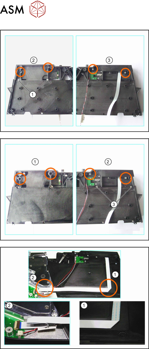
For 16-24mm feeder modules only
► Fix the operating panel with the two screws
marked in the diagram with (1).
► Fix the operating panel with the self-cutting Torx
screws marked in the left-hand diagram (2).
► Turn the foil disposal drive over, together with the
foil container.
► Fix the operating panel with the self-cutting Torx
screws marked in the right-hand diagram (3).
For 32-88mm feeder modules only
► Fix the operating panel with the self-cutting Torx
screws marked in the left-hand diagram (1).
► Turn the foil disposal drive over, together with the
foil container.
► Fix the operating panel with the self-cutting Torx
screws marked in the right-hand diagram (2).
► Fix the operating panel with the two screws
marked in the diagram at (3).
► Insert the foil disposal drive, together with the foil
container, into the feeder module.
Run the cable as shown in the example diagram (8
mm feeder module).
► (1) Run the flat ribbon cable vertically downwards
and carefully fold it to the left.
► (2) Carefully fold the flat ribbon cable as marked
in the diagram.
Make sure that the blue surface at the end of the
cable is at the top.
► Thread the other cable under the flat ribbon
cable, to the second connection.
6 Repairing the X Feeder modules
6.7 Operating Panel Assembly
Service Manual SIPLACE X-Feeder 4 - 88 mm 11/2017 85
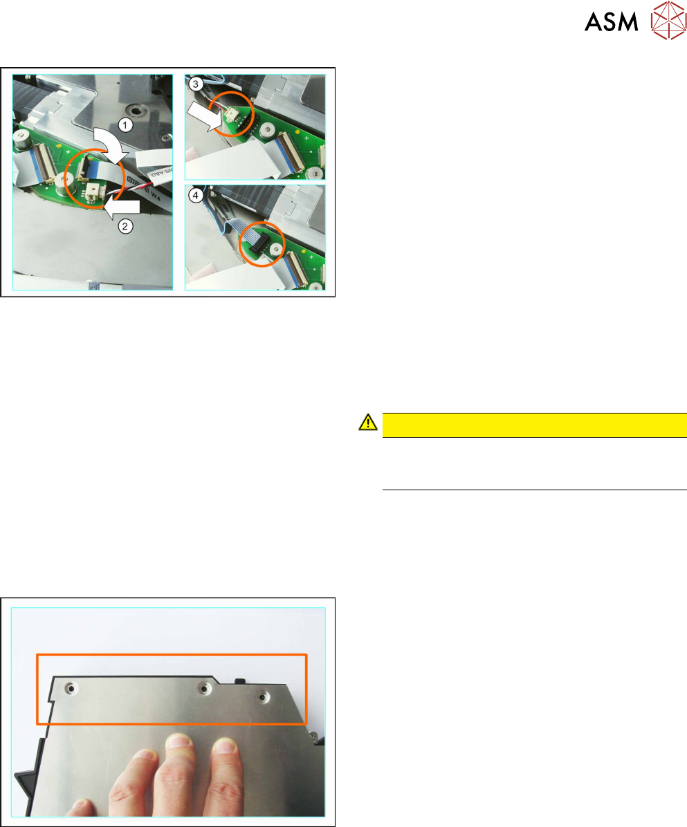
► (1) Insert the flat ribbon cable into the connection,
as far as the stop.
Make sure that the blue surface at the end of the
cable is at the top and that the flat ribbon cable
lies straight in the connection.
► Swing the lock on the connection down onto the
flat ribbon cable.
Make sure that the flat ribbon cable is fitted firmly
in the connection. Tug gently on the cable to
check.
► Check again whether the flat ribbon cable is fitted
straight in the connection.
If necessary, open the lock and correct the posi-
tion of the cable before closing the lock again.
► (2) and (3)
Carefully insert the connector in the direction of
the arrow, as far as the stop, into the connection
shown.
Make sure that the smooth side of the connector
is at the top.
CAUTION!
Do not push the connector with force into the
connection, otherwise individual pins may
break off or be distorted.
.
► (4) Insert the other connector into the connection
marked in the diagram.
► Fit the left side cover into place (see 6.3.2 "Fitting
the Left Side Cover" [}24]).
► Carefully place the feeder module down on its left
side.
► Position the foil container so that it is aligned
against the side cover.
6 Repairing the X Feeder modules
6.7 Operating Panel Assembly
86 Service Manual SIPLACE X-Feeder 4 - 88 mm 11/2017
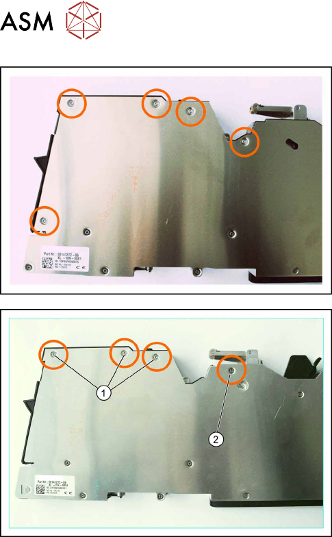
Example diagram for X feeder modules with 16mm
width
► Fix the mushroom head cutting screws marked in
the diagram (2.5 x 7.5mm Torx).
Example diagram for X feeder modules with 24-88mm
width
► Loosen the screws marked in the diagram.
(1) Mushroom head cutting screw (2.5x7.5mm)
Torx
(2) Cylinder head Phillips screw (2.5x5mm)
► Now fit the rocker (see 6.6.2.2 "Fitting the Rocker
(4 - 88 mm)" [}70]).