YG100R_Ope_E - 第32页
1-4 1 Part names and functions 2 . O p e r a t i o n p a n e l a n d d a t a i n p u t u n i t S t a n d a r d m a c h i n e s a r e e q u i p p e d w i t h a n o p e r a t i o n d i s p l a y, o p e r a t i o n p a n e …
1-3
1
Part names and functions
n
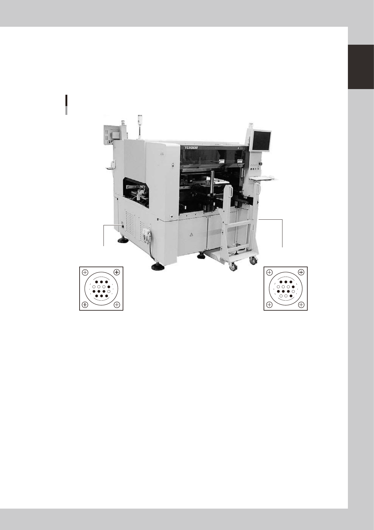
Connection between machines (input/output signals between machines)
The mounter ejects the finished board when it receives a signal from the machine in the next process, and then sends a
signal to the machine in the preceding process to request another board. The interface connector labeled "NEXT
INTERFACE" connects to the machine in the next process, and the interface connector labeled "PREVIOUS INTERFACE"
connects to the machine in the preceding process.
In the case of standard machines of right-to-left flow, the PREVIOUS INTERFACE connector is located on the right side of
the machine, and the NEXT INTERFACE connector on the left side.
PREVIOUS INTERFACE
(For connection to
upstream machine)
NEXT INTERFACE
(For connection to
downstream machine)
Connector : AMP 206043-1 (14-pin receptacle)
Machine-to-machine interface connectors
14
11
12
7
4
8
3
1
14
11
12
7
4
8
1
3
23004-M1-00
n
Feeder setup section
Mainly tape feeders are installed here. (See "4.1 Supplying components from feeder plates" for details.
n
Component supply indicator (option)
Indicates the position (front or rear) where an error has occurred or components should be supplied.
1-4
1
Part names and functions
2. Operation panel and data input unit
Standard machines are equipped with an operation display, operation panel buttons, a keyboard and a
mouse on the front and rear (option) of the machine, to operate the machine and make data settings. The
functions of these units are explained below.
Operation display (touch screen is optional)
Mouse
Keyboard
Operation panel button
Operation panel and data input unit
23101-M1-00
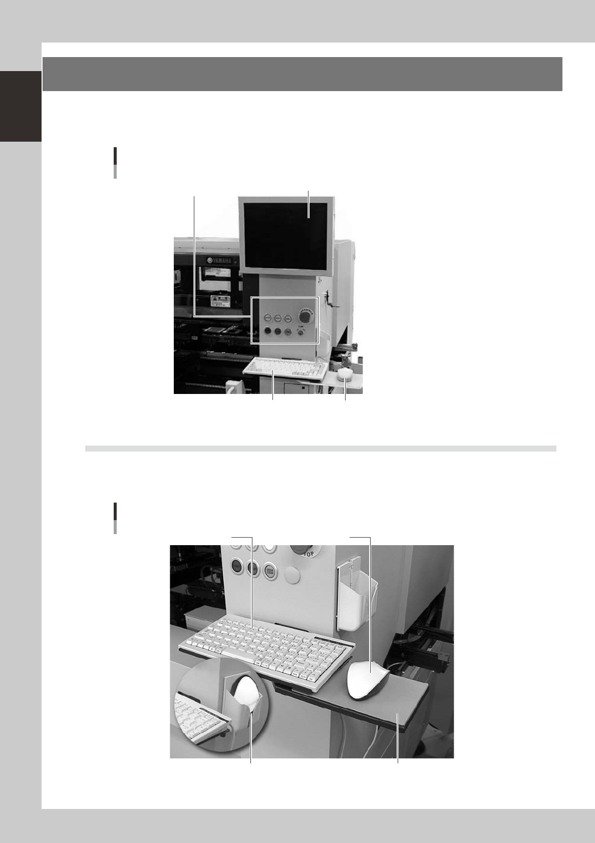
2.1 Keyboard and mouse
This machine is equipped with a keyboard and mouse as standard features to operate the machine or edit data
settings. To select a menu button or parameter item on the operation screen, click it with the left mouse
button.
Keyboard and mouse
Keyboard
Mouse
Mouse in holder
Mouse pad
23103-M1-00
1-5
1
Part names and functions
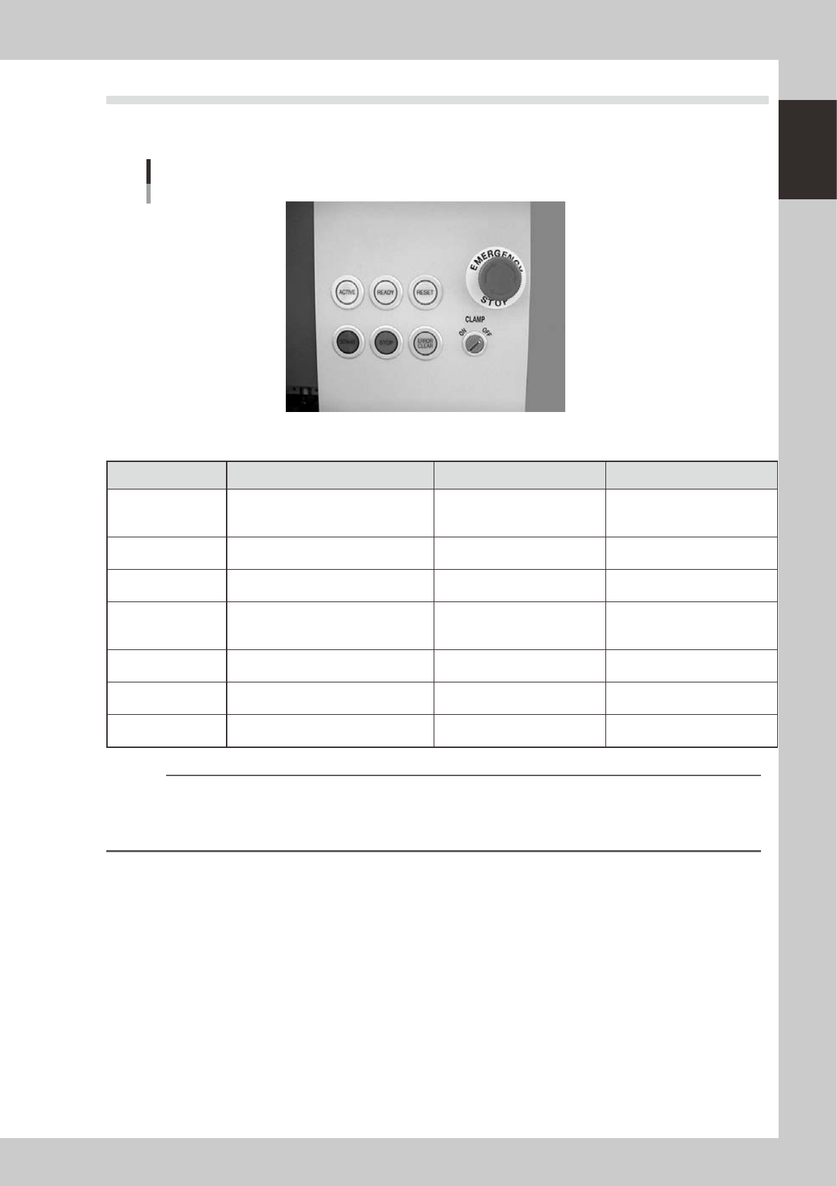
2.2 Operation panel buttons
The operation panel buttons are provided on the front and rear (option) of the machine to run major commands
frequently used to operate the machine. Each button is lit while turned on.
Operation panel buttons
23102-M1-00
n
Operation panel button functions
Button name Use the button to: OFF ON
ACTIVE
Enable other keys. (The front and rear
[ACTIVE] keys cannot be turned on
simultaneously.)
• After machine has started.
• The other table has access
rights to operate machine.
• This table has access rights to
operate machine.
READY
Release emergency stop and turn the
servo on.
• SERVO OFF
(Motor power OFF)
• SERVO ON
(Motor power ON)
RESET
Stop automatic operation and return to
standby for board production.
• Machine is in normal operation
or stopped.
• Machine has been reset.
START
Perform component placement
according to board data.
• Machine is stopped.
• Machine is in normal operation.
[Flash]
Pause or step operation
STOP
Interrupt automatic operation. (Press
START to resume operation.)
• Machine is in normal operation. • Error occurred.
ERROR CLEAR
Stop buzzer sound and clear error
screen.
• Machine is in normal operation. • Error occurred.
EMERGENCY STOP
Trigger emergency stop. Turn to the
right to release it.
n
NOTE
The [ACTIVE] button is provided on both front and rear (option) panels, but cannot be turned on simultaneously. This
means that the [READY], [START], [ERROR CLEAR] and [RESET] buttons are enabled only when the [ACTIVE] key on the
same panel is turned on. (The [STOP] button can be used when the [ACTIVE] button is either on or off.)
The keyboard is enabled only when the [ACTIVE] key on the front panel is on.