YG100R_Ope_E - 第40页
1-12 1 Part names and functions n M o u n t e r s i d e Switch and sensors on mounter 3 1 2 4 23 1 1 9 - M 1 -0 0 1 C l a m p O N / O F F s w i t c h A f t e r i n s t a l l i n g t h e f e e d e r e x c h a n g e c a r …
1-11
1
Part names and functions
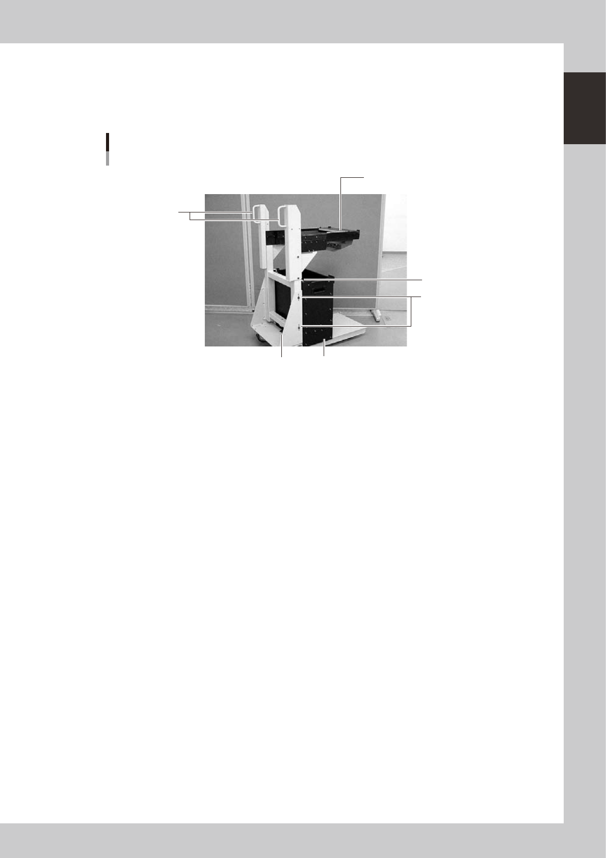
4.1.2 Feeder exchange carriage
The feeder exchange carriage allows feeder setup in advance for the next production boards. The feeders on
the feeder exchange carriage can be changed at one time.
n
Feeder exchange carriage
External view of feeder exchange carriage
1
2
5
4
6
3
23118-M1-00
1 Handle
Use this handle to move and position the feeder exchange carriage.
2 Feeder plate
Up to 20 or 24 tape feeders (8mm tape feeders) can be installed on this feeder plate.
3 Vertical clamp bolts
If necessary to adjust the feeder plate height, loosen these bolts and change their clamping positions by turning the
height adjustment bolt 6 to match the mounter height.
4 Empty tape dump box (option)
This box is for catching empty tape after components have been picked up.
5 Empty tape dump box holder
This holder prevents the tape dump box (option) from falling.
6 Height adjustment bolt
After loosening the vertical clamp bolts 3, turn this bolt to adjust the feeder plate height to match the mounter height.
1-12
1
Part names and functions
n
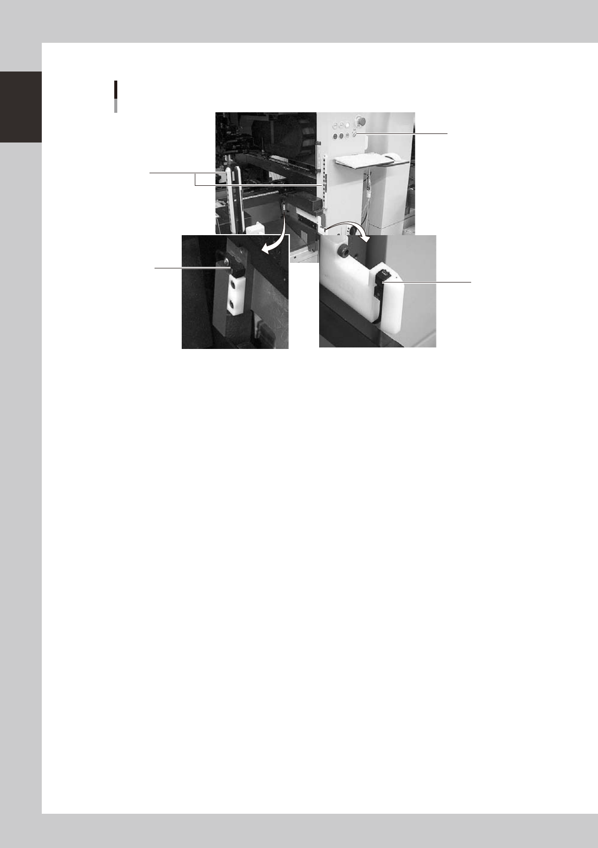
Mounter side
Switch and sensors on mounter
3
1
2
4
23119-M1-00
1 Clamp ON/OFF switch
After installing the feeder exchange carriage into the mounter, turn this switch to the left (ON) to raise the feeder plate of
the feeder exchange carriage and automatically clamp it into the position. To unclamp, turn this switch to the right (OFF).
2 Forward end sensor
When the feeder exchange carriage is fully installed into the mounter, the green LED on this sensor lights up.
3 Area sensor for non-stop operation (option)
This safety area sensor is attached to mounters with a non-stop function. When the feeder exchange carriage is installed
into the mounter, the entrance sensors located at the front (or rear) of the mounter detect the feeder exchange carriage
and turn off this area sensor function.
4 Entrance sensor for non-stop feeder exchange carriage (option)
This sensor is attached to the front (or rear) of mounters with a non-stop function. When the feeder exchange carriage is
installed into the mounter, this sensor detects the feeder exchange carriage and turns off the area sensor function to
permit removing and installing the feeder exchange carriage even during automatic operation.
1-13
1
Part names and functions
4.2 Supplying components from trays
There are two types of external tray changers. One type, called "dYTF", supplies tray components using its pick
& place head and relay station. The other type, "wATS" and "sATS", utilizes a head of the connected surface
mounter.
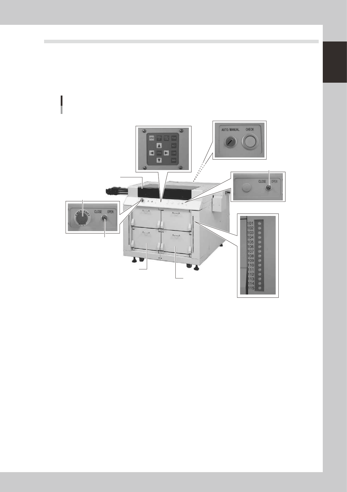
4.2.1 dYTF main unit
Major part names and their functions of dYTF are explained below.
8. Conveyor operation switch
dYTF main unit
Magazine door side
7. Pallet indicator
1. Safety cover
2. Magazine door (stage 1)
3. Magazine door (stage 2)
4. Emergency stop button
5. Door switch (stage 1)
5. Door switch (stage 2)
6. Teaching panel
23120-M1-00
1. Safety cover
When this cover is opened with the power on, it triggers emergency stop. Keep this cover closed during operation.
2. Magazine door (stage 1)
Open this door when replacing a pallet or a magazine on stage 1. The upper door is for Magazine 1 and the lower door
is for Magazine 2.
3. Magazine door (stage 2)
Open this door when replacing a pallet or a magazine on stage 2. The upper door is for Magazine 1 and the lower door
is for Magazine 2.
4. Emergency stop button
Pressing this button triggers emergency stop, the same as the emergency stop buttons on the mounter.
5. Door switch
Placing this switch in "OPEN" unlocks the magazine door, so you can open it. When this switch is in "CLOSE", the door
is locked and the door switch lamp lights up.
6. Teaching panel
Use the operation keys on this panel when teaching the tray component positions on a pallet.