YG100R_Ope_E - 第46页
1-18 1 Part names and functions 5 . Pa l l e t i n d i c a t o r l a m p T h e i n d i c a t o r l a m p f o r t h e p a l l e t N o . s e t i n t h e p a r t s i n f o r m a t i o n i s l i t u p . W h e n t h e t r a y…
1-17
1
Part names and functions
4.2.3 wATS main unit
The wATS is installed in the rear of the surface mounter. Major part names and their functions of sATS are
explained below.
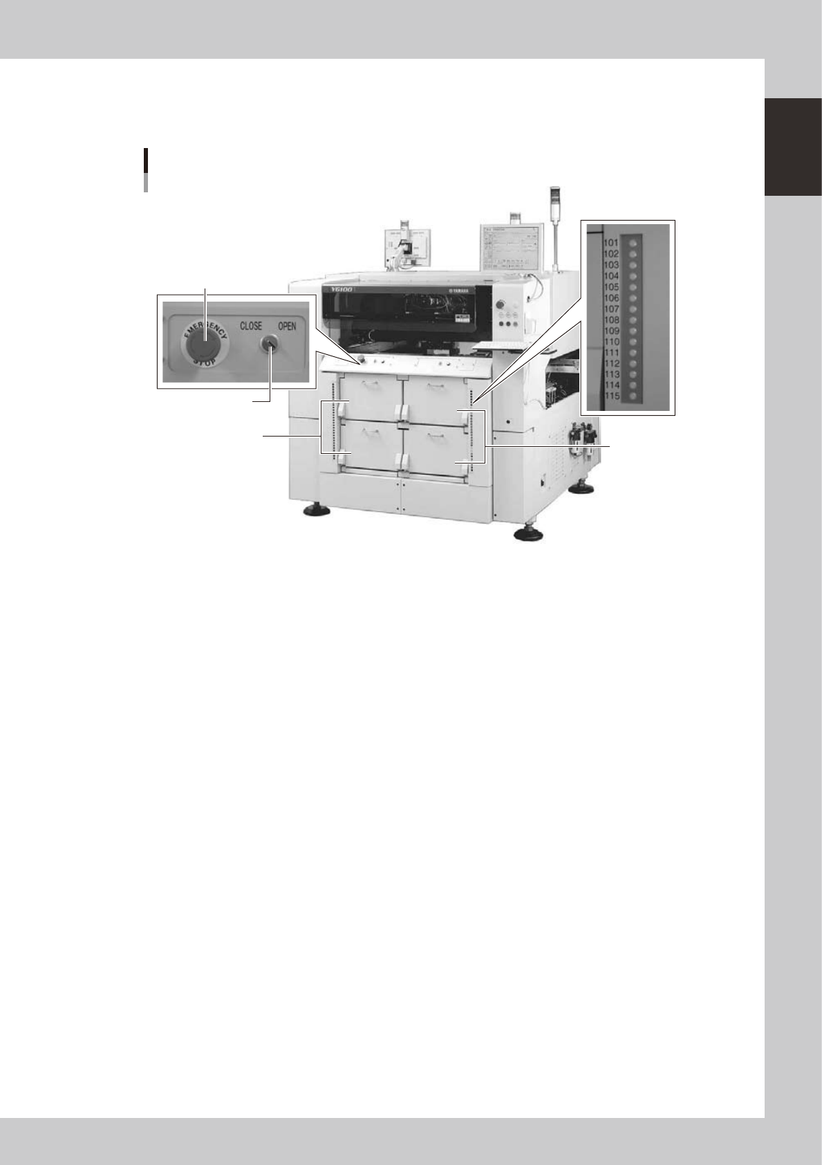
wATS main unit
Mounter rear side
1. Magazine door
(stage 1)
5. Pallet indicator
2. Magazine door
(stage 2)
4. Door switch
3. Emergency stop button
23126-M1-00
1. Magazine door (stage 1)
Open this door when replacing a pallet or a magazine on stage 1. The upper door is for Magazine 1 and the lower door
is for Magazine 2.
2. Magazine door (stage 2)
Open this door when replacing a pallet or a magazine on stage 2. The upper door is for Magazine 1 and the lower door
is for Magazine 2.
3. Emergency stop button
Pressing this button triggers emergency stop, the same as the emergency stop buttons on the mounter.
4. Door switch
Placing this switch in "OPEN" unlocks the magazine door, so you can open it. When this switch is in "CLOSE", the door
is locked and the door switch lamp lights up. The door switches for stage 1 and stage 2 can be operated independently.
1-18
1
Part names and functions
5. Pallet indicator lamp
The indicator lamp for the pallet No. set in the parts information is lit up. When the tray components on a pallet are used
up, the indicator lamp for that pallet No. flashes (see below). A total of 60 indicator lamps are provided since 15
indicator lamps are used for each magazine.
After you set new pallets in the magazines, press the flashing indicator buttons to reset them.
n
Relation between pallet indicator numbers and magazines
Pallet indicator number Magazine
1 to 15 Magazine 1 for stage 1
16 to 30 Magazine 2 for stage 1
101 to 115 Magazine 1 for stage 2
116 to 130 Magazine 2 for stage 2
n
Pallet indicator lighting pattern
Pallet condition Component condition Indicator status
One component type on one pallet
Components have been supplied. ON
Used up all components. Flashing
Components are currently being used. ON
Two or more components types on
one pallet
All components on pallet have been supplied. ON
Used up all components. Flashing
Used up at least one type of component. Flashing
Components to be used are not specified in board data. OFF
1-19
1
Part names and functions
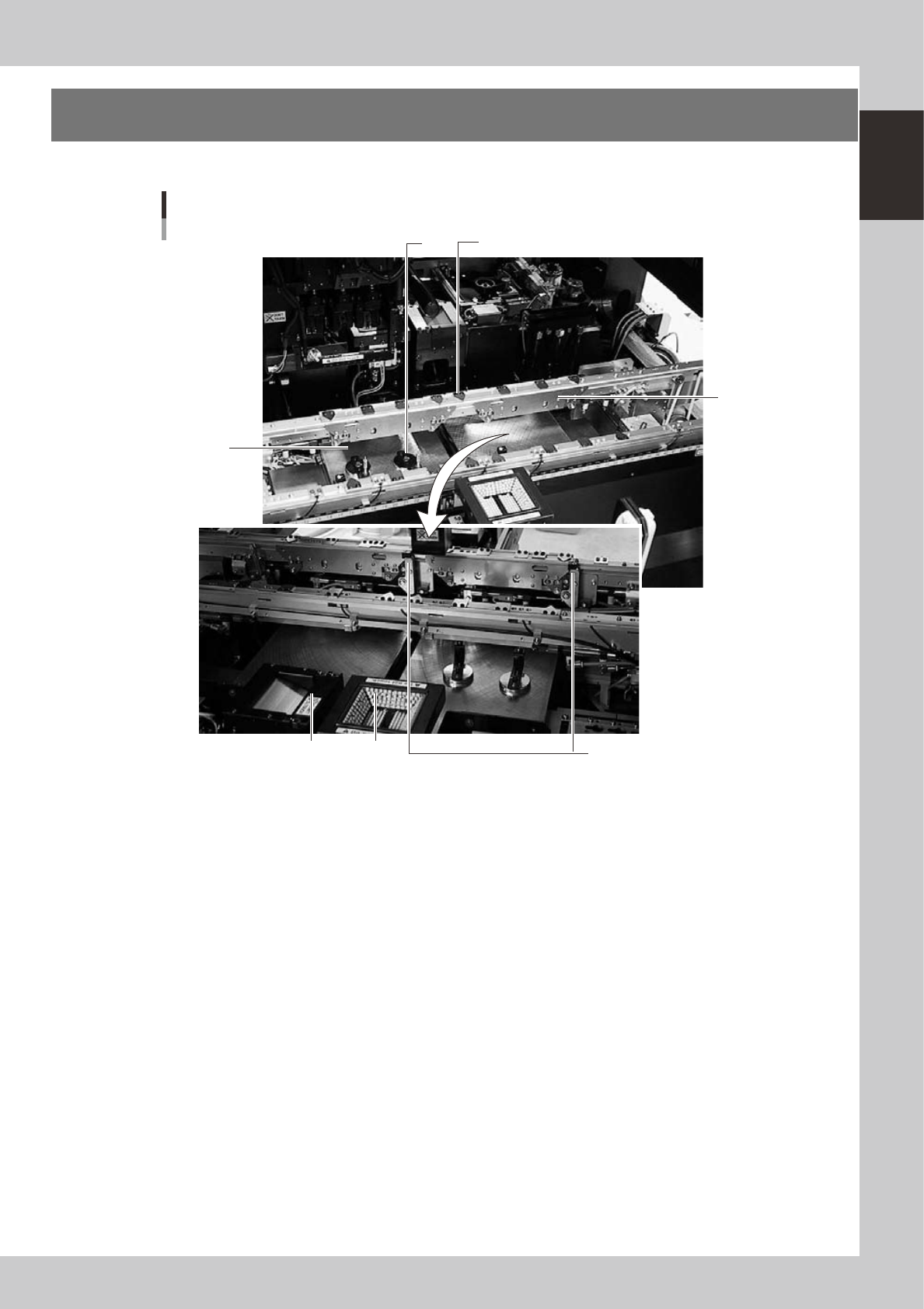
5.
Conveyor unit and component recognition system
The conveyor unit used to clamp a board in mounting position is described below.
4
5
2
1
7 6
Conveyor unit
3
Viewed from the rear side of a machine
23110-M1-00
1. Main stopper
When a board is carried in on the conveyor, the main stopper halts travel of the board in the component mounting
position. (Double stopper is optional.)
2. Push-up plate
The push-up plate clamps the board up against the conveyor rails, with the supporter pins attached by magnet on the
push-up plate.
3. Push-up pins
These pins are arranged on the push-up plate and secure the board by pushing it up from the bottom.
4. Board hold plate
These plates hold the edges of the board from above when the board is clamped in the mounting position.
5. Board edge clamp unit
This unit clamps the board by pushing its edges up against the board hold plates.
6. Multi-vision camera
One camera each is installed on the front and rear of the machine to perform component recognition.
7. Coplanarity checker (option)
Works in conjunction with a multi-vision camera to measure lead linearity and coplanarity of lead components or BGA
components.