YG100R_Ope_E - 第51页
1-23 1 Part names and functions 8 . O t h e r o p t i o n s 8 . 1 S i d e - v i e w c a m e r a T h e s i d e - v i e w c a m e r a i s i n s t a l l e d o n t h e X - a x i s a t t h e f r o n t o f t h e m u l t i - v …
1-22
1
Part names and functions
7.1 Performing a nozzle shaft blow
This section explains how to manually perform a nozzle shaft blow at any desired timing.
1
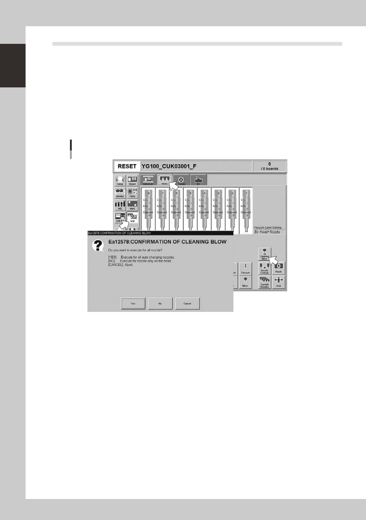
Open the [Unit] – [Head] tab screen.
2
Press the [Cleaning Blow] button.
A confirmation dialog box appears asking how you want to perform nozzle shaft blow, so press [Yes] or
[No]. (Press [Cancel] if you want to cancel nozzle blow.)
Pressing [Yes]:
Cleans all nozzles that are automatically changeable and set for cleaning blow.
Pressing [No]:
Makes a cleaning of nozzles that are currently attached to the head and set for cleaning blow.
Nozzle shaft blow
24100-M1-00
n
Safety checks
The nozzle shaft blow function also contains the following safety checks.
• Nozzle shaft blow interruption alarm
The head immediately rises if operation stops during nozzle shaft blow due to emergency stop or an interlock triggering.
If the head rises but the air blow still continues, then the nozzle might come loose from the head. To prevent this, a
confirmation dialog box appears if the machine operation stopped during nozzle shaft blow.
• Nozzle sensors to check whether a nozzle is left on the blow station
The nozzle shaft blow function forces high-pressure air through the nozzles during cleaning, so the nozzles might come
loose from the head if machine operation stops during nozzle blow. If a nozzle comes loose from the head and remains
on the blow station while the automatic operation still continues, then the nozzle left on the blow station might interfere
with other heads or with the multi-max unit. To prevent this, nozzle sensors are installed so that the machine constantly
monitors whether a nozzle is left on the blow station.
An “interlock error” is issued if any of these sensors detects a nozzle on the blow station at any time other than when the
head is lowered during nozzle blow. The machine operation is then disabled.
1-23
1
Part names and functions
8. Other options
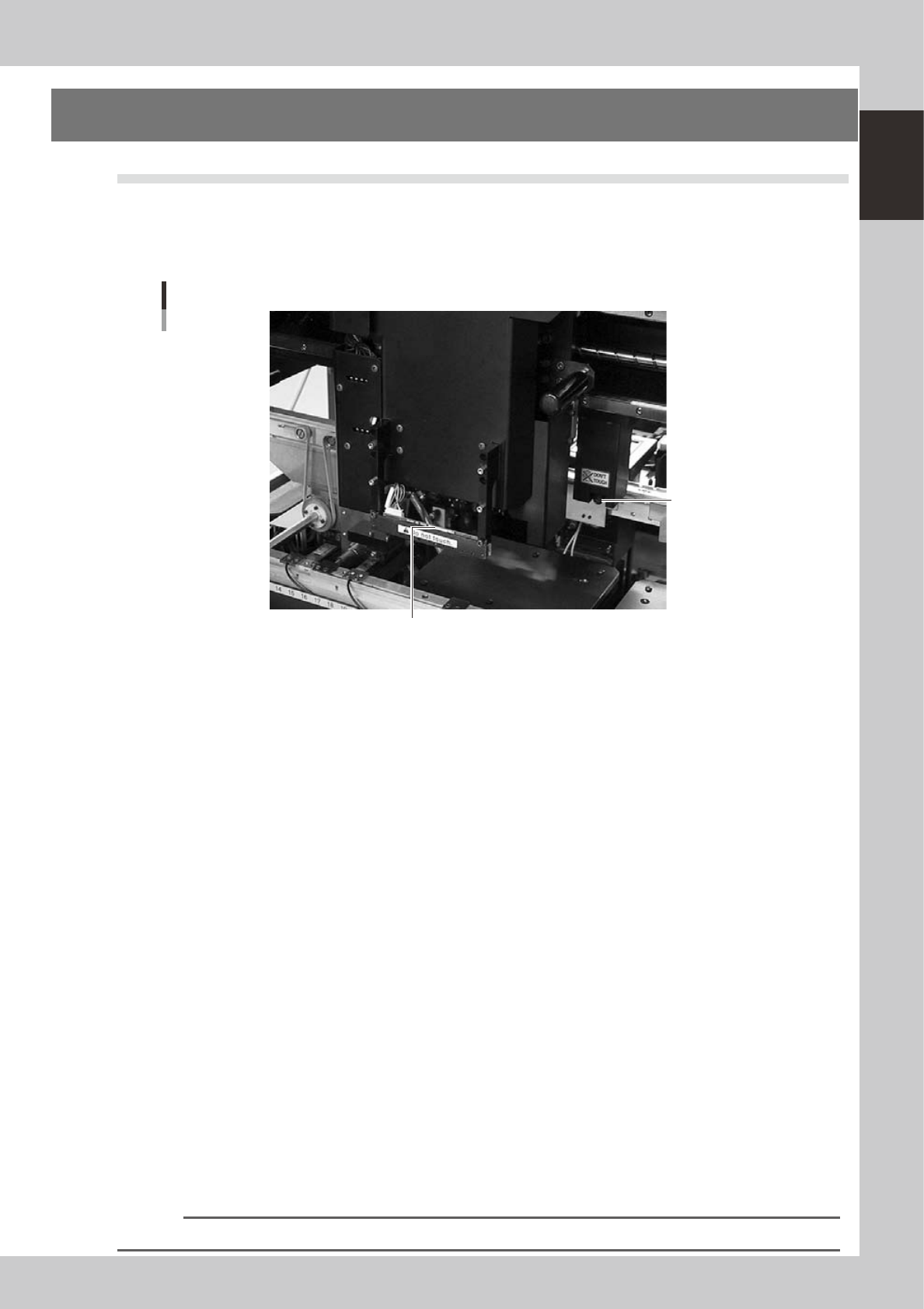
8.1 Side-view camera
The side-view camera is installed on the X-axis at the front of the multi-view camera. The side-view camera
recognizes horizontal images such as for the component pickup status, by using lighting installed for the
side-view camera. This allows the machine to detect component pickup errors and abnormal pickup, or find
dirt or debris adhering to the nozzle.
Side-view camera
Side-view camera
Lighting unit (with cover removed)
23114-M1-00
The side-view camera has the following functions:
n
Pickup error detection function
Normal mode
Detects component pickup errors to prevent "no placement errors".
Normal mode operates even when nozzles are changed after nozzle cleaning, etc.
Detail mode
Detects component pickup errors to prevent "no placement errors".
Checks for abnormal component pickups such as tilted, vertical or horizontal pickups based on the component thickness
tolerance set by the users.
n
Dirty nozzle sensing function
If the side-view camera shows "no component" even when the multi-view camera shows "component present", the
machine determines that the nozzle tip is "dirty" and a warning message appears. This serves as an accurate guide for
nozzle cleaning periods.
n
Component discard skip
This function skips the discard operation when the side-view camera shows "no component".
This eliminates unneeded operation when no component was picked up and prevents a loss of cycle time during
production.
n
Remaining component check function
This detects whether a component still remains at a nozzle tip after components were mounted or discarded.
n
Inverted component check function
In the recognition process after a component is picked up by a nozzle, this function checks if the front and back sides of
the component are inverted. It also simultaneously checks if that component size fits within the angle-of-view of the
side-view camera.
An error message appears if recognition shows the component front and back sides are inverted or that component will
not fit within the angle-of-view.
n
NOTE
Refer to "Programming Manual" for side-view camera parameter settings.
1-24
1
Part names and functions
8.2 QFP dump station
The QFP dump station (hereafter called dump station) is a QFP recovery conveyor designed to attach to the
feeder plate of a YAMAHA surface mounter. If a QFP is judged defective by vision camera recognition, that
QFP is temporarily placed on this dump station without being damaged. The QFP placed on the dump station
is then conveyed back at a specified feed pitch. When the dump station becomes full, the memory counter or
overflow sensor detects it and displays an error message before the next defective QFP is returned to the dump
station.
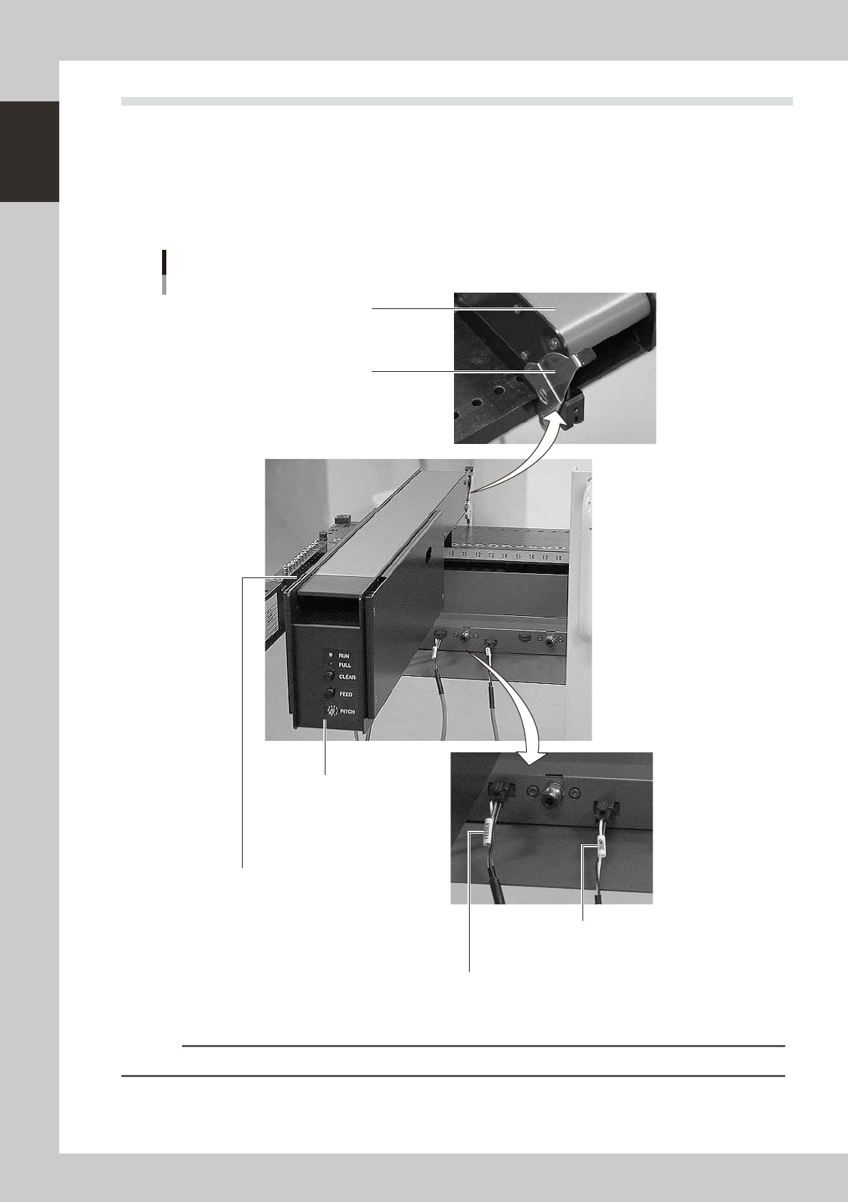
Photographs below show major parts and functions of the dump station.
Clamp lever
Use this lever to lock or unlock
the dump station to the feeder plate.
DUMP harness (signal cable)
Used to interface between the dump station
and the mounter for exchanging signals.
FEEDER harness (power supply cable)
Supplies power to the dump station from the mounter.
Manual operation panel
Use the switches on this operation panel
to set the feed pitch, move the belt at the
specified pitch and clear the count.
The LED lamps also show the
operation status.
Overflow sensor (option)
QFPs placed on the dump station
are carried back by the belt conveyor.
When a QFP arrives at the end of
the dump station, this overflow sensor
detects it and displays an error message.
Conveyor belt
Conveys QFPs placed on the
dump station at a specified feed pitch.
Major parts and functions
23104-M1-00
n
NOTE
For how to use the QFP dump station, refer to the option manual "QFP dump station".