YG100R_Ope_E - 第77页
2-24 2 Basic operation 3 . 4 . 3 B o a r d h o l d p l a t e s T h e b o a r d h o l d p l a t e s h o l d b o t h e d g e s o f t h e b o a r d f r o m a b o v e w h e n t h e b o a r d i s s e c u r e d i n t h e m o u…
2-23
2
Basic operation
3.4.2 Conveyor width
Adjust the conveyor width to match the board width to be produced.
1
Select the board data.
See the description in "1. Starting production" in Chapter 3.
n
NOTE
When the conveyor width is set in the board data, the conveyor width will be automatically adjusted. Skip the
following steps.
2
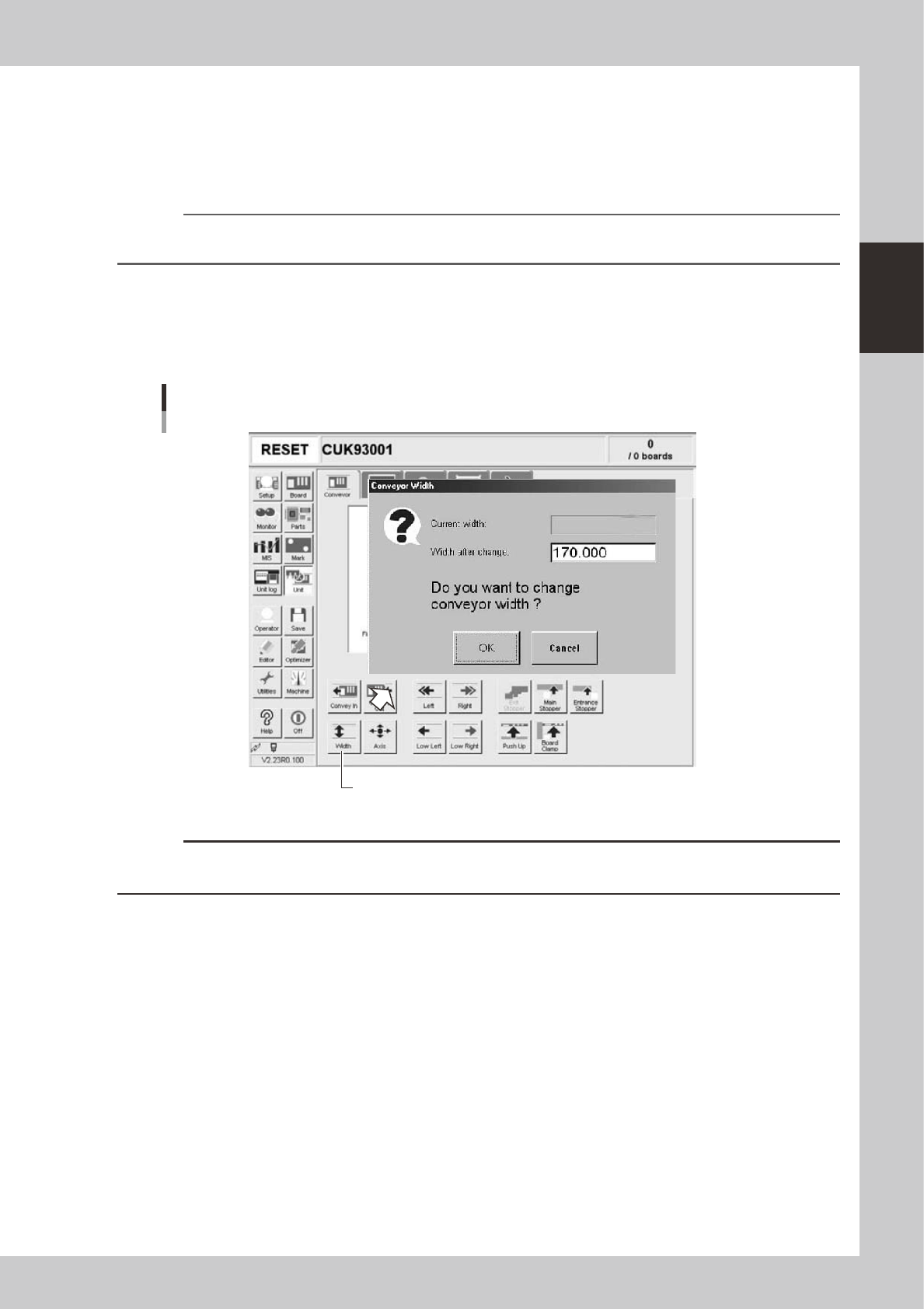
Open the [Unit]-[Conveyor] screen.
3
Press the [Width] button.
The "Conveyor Width" dialog box appears. Check the conveyor width (units: mm) and press the [OK]
button. The conveyor rail automatically changes to the specified width.
[Width] button
"Conveyor Width" dialog box
24210-M0-00
c
CAUTION
When push-up pins are set on the push-up plate, make sure that they do not touch the conveyor rails while adjusting
the conveyor width.
2-24
2
Basic operation
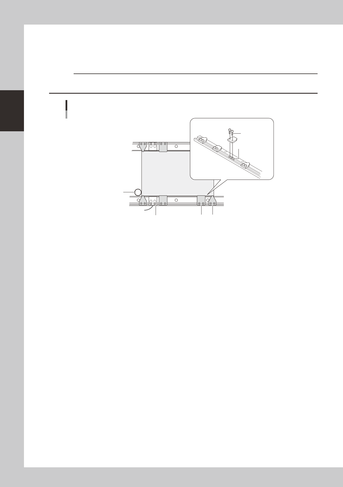
3.4.3 Board hold plates
The board hold plates hold both edges of the board from above when the board is secured in the mounting
position. These board hold plates are installed with M3 screws on the conveyor rails. Arrange them at roughly
equal spacing along the length of the board.
c
CAUTION
On the fixed conveyor rail, fiber sensor holders that resemble the board hold plates are also installed. Do not change
the positions of these fiber sensor holders when arranging the board hold plates.
Board
Phillips screw
(M3)
Fiber sensor holder
Main stopper
Board hold plate installation
Movable conveyor rail side
Fixed conveyor rail side
Board hold plate
Board hold plates
M3 nut
23205-M0-00
2-25
2
Basic operation
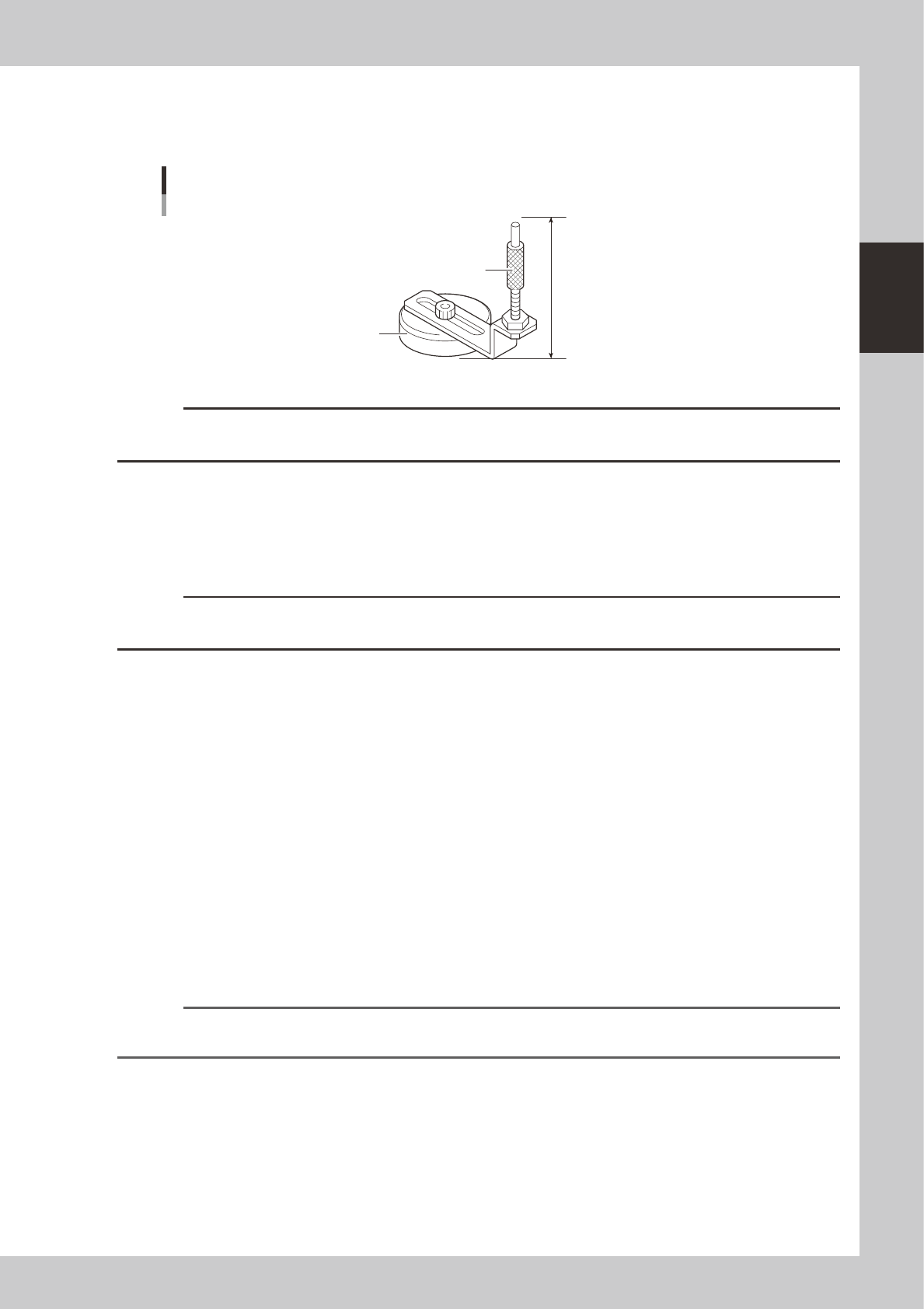
3.4.4 Push-up pins
The push-up pins are attached on the push-up plate by a magnet and used to correct downward warping of the
board.
64mm
Support pin
Pushup pin
Magnet stand
23204-M0-00
c
CAUTION
The push-up pin height from the bottom of the magnet to the top of the pin shaft is set to 64mm. Do not change this
height.
e
1
Press the emergency stop button.
2
Place the push-up pins in the correct positions on the push-up plate.
Considering the shape and size of the board, place the push-up pins on the push-up plate so that they
uniformly support the board, including the edge of the board.
c
CAUTION
Set the push-up pins in positions where they will not interfere with the conveyor rails and other parts when the push-up
plate is raised.
3
Set a board on the conveyor.
Press the [Main Stopper] button on the [Unit] - [Conveyor] screen to raise the main stopper. Then set a
board on the conveyor and place it against the main stopper.
4
Cancel emergency stop.
Release the emergency stop button by turning it clockwise and press the [READY] button on the
operation panel.
5
Raise the push-up plate.
Check safety and press the [Push Up] button to raise the push-up plate. The board thickness input box
then appears. Enter the thickness of the board in millimeters and press the [OK] button. The push-up
plate moves up to secure the board.
e
6
Check that the board is uniformly clamped on the conveyor.
After pressing the emergency stop button, lightly tap on the board and also check for warping of the
board from the side. If the board is supported evenly with no warping, the adjustment is okay.
At this point, if the tips of the push-up pins do not reach the bottom of the board or the pins are pushing
the board up too much, the push-up plate height should be adjusted.
Reference
It may be convenient to mark the positions of the push-up pins on the plate (with adhesive tape, magic marker, etc.)
for each board type.