00197961-01_UM_JTF-MW_on_SIPLACE_E_en_FINAL - 第25页
Technical Data of the SIPLACE JTF-MW 3.1.1 Location of Electrical Parts Communication, Signals User Manual JTF-MW on SIPLACE E 25 3.5 3 . 5 C o m m u n ic a t io n , S ig n a ls Communication, Signals 3.6 3 . 6 A m b ie …

Technical Data of the SIPLACE JTF-MW
Pneumatics 3.1.1 Location of Electrical Parts
24 User Manual JTF-MW on SIPLACE E
3.4
3.4 Pneumatics
Pneumatics
Description Unit
JEDEC Tray capacity 15 levels of cookie tray, each handles 2 JEDEC
trays
=> 30 thin JEDEC Standard Trays
Standard JEDEC Tray Type JEDEC Standard No. 95-1, IEC 60286-5
JEDEC Tray width 135.9 + 0.25/-0.13 mm
JEDEC Tray length 322.6 + 0.25/-0.13 mm
Tray thickness See below (total Max 35 mm when skip 2 levels,
Max 11.8 mm
JEDEC Tray Material Trays made of plastic, opaque materials
JEDEC Tray flatness ≥ 0.8 mm over entire surface
JEDEC Tray warpage ≤ 2 mm
Position accuracy Edge of tray 0.05 mm repeatable.
Tray Exchange (fast)
Average try exchange time 9 s
Tray Exchange (Slow)
For sensitive components
About 30 – 50% slower compared to fast.
Total weight of cookie tray 30 kg
Max weight per tray 2 kg +/- 10%.
For heavily loaded trays the balance must be in the
center of the tray.
Maximum force on tray 2 N
Orientation of trays Keyed
Component size vs. Pocket size JEDEC Standard No. 95-1
Mean Time Between Failure (MTBF) 1344 h
Mean Time To Repair (MTTR) 30 minutes
Mean Time Between Maintenance (MTBM) 200 h
Mean Time To Maintain (MTTM) 15 minutes
Mean Time Between Assist (MTBA) 4 h
Mean Time To Assist (MTTA) 2 minutes
Pneumatics Description
Connection 4 mm tube
Pressure 5.0 – 10.0 bar
Compressed air consumption < 28.3 l/min (1SCFM)
Technical Data of the SIPLACE JTF-MW
3.1.1 Location of Electrical Parts Communication, Signals
User Manual JTF-MW on SIPLACE E 25
3.5
3.5 Communication, Signals
Communication, Signals
3.6
3.6 Ambient Conditions
Ambient Conditions
3.7
3.7 Electrical Data
Electrical Data
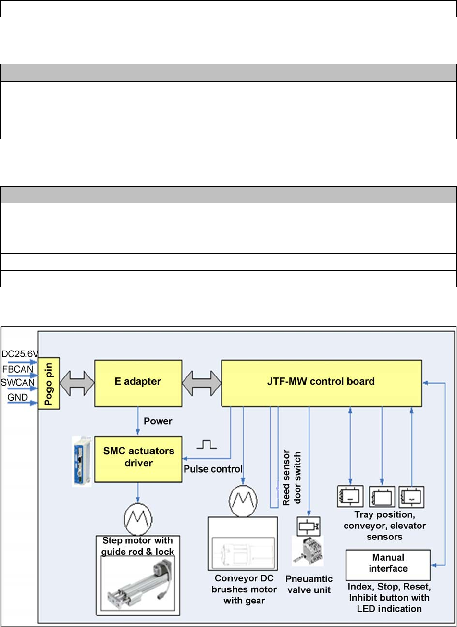
Electrical components, motors, sensors and buttons, etc. are integrated in the SIPLACE JTF-MW.
It consists of the following functional blocks:
Functional diagram of electrical system in the SIPLACE JTF-MW
Communication interface ASM pogo pin interface, CAN bus
Ambient conditions Description
Relative humidity 30% to 75 % (no higher than 45% on average to
prevent any possibility of condensation on the ma-
chine)
Temperature 10 °C to 35 °C / 50 °F to 95 °F
Power consumption
Peak 5 A
Standby 1 A
During tray exchange 1.3 A
Fuse 1.85 A
Voltage supply 24 VDC ± 10%
Technical Data of the SIPLACE JTF-MW
Electrical Data 3.1.1 Location of Electrical Parts
26 User Manual JTF-MW on SIPLACE E