00197961-01_UM_JTF-MW_on_SIPLACE_E_en_FINAL - 第30页
Setting up and Commissioning Preparatory Work 30 User Manual JTF-MW on SIPLACE E 4.5.2 4 . 5 . 2 R e t r o f it t in g W o r k o n t h e H o s t M a c h in e Retrofitting Work o n the Host Machine Adapt the host machine …
Setting up and Commissioning
Preparatory Work
User Manual JTF-MW on SIPLACE E 29
Component height restrictions for different head combinations
4.5
4.5 Preparatory Work
Preparatory Work
The SIPLACE JTF-MW will be installed on a moveable table system [03105475-xx] (COT) on location
2B in a SIPLACE E machine.
The COT and the host machine must be adapted before the SIPLACE JTF-MW can be installed:
▪ "4.5.1 Retrofitting Work on the COT" [ ➙ 29]
▪ "4.5.2 Retrofitting Work on the Host Machine" [ ➙ 30]
4.5.1
4.5.1 Retrofitting Work on the COT
Retrofitting Work on the COT
Adapt the COT using the following retrofitting kit:
▪ JTF-MW Table Kit [03115273-xx].
Head configuration SIPLACE CP6
& SIPLACE PP
SIPLACE CP12
& SIPLACE PP
SIPLACE TH or
SIPLACE PP
Comments
Max. height of component and
tray
16 mm 16 mm 25 mm Same restric-
tions as for
manual tray.
NOTICE
Collision avoidance
As the machine has no sensors to check the component height in the tray carrier, it is in the
responsibility of the operator to ensure that the height restriction is not violated.
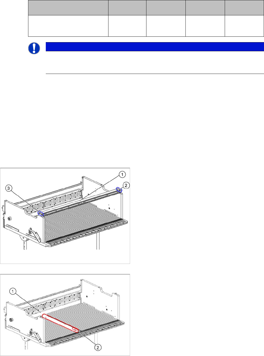
► On the original feeder locking bar (1), remove the
screws in positions (2) and (3).
► Remove the feeder locking bar.
1. Original guide profile removed
2. Installation location for the locking bar mount
► In the marked area (1), remove the original guide pro-
file.
Setting up and Commissioning
Preparatory Work
30 User Manual JTF-MW on SIPLACE E
4.5.2
4.5.2 Retrofitting Work on the Host Machine
Retrofitting Work on the Host Machine
Adapt the host machine using the following retrofitting kits:
▪ JTF-MW Frame Kit [03117595-xx]
▪ Tubing set for JTF-MW [03120613-xx]
▪ Empty tape duct ETD 25 mm right [03110329-xx]
► At location 2B, unload the COT and remove it from the machine.
Connecting the tubing set
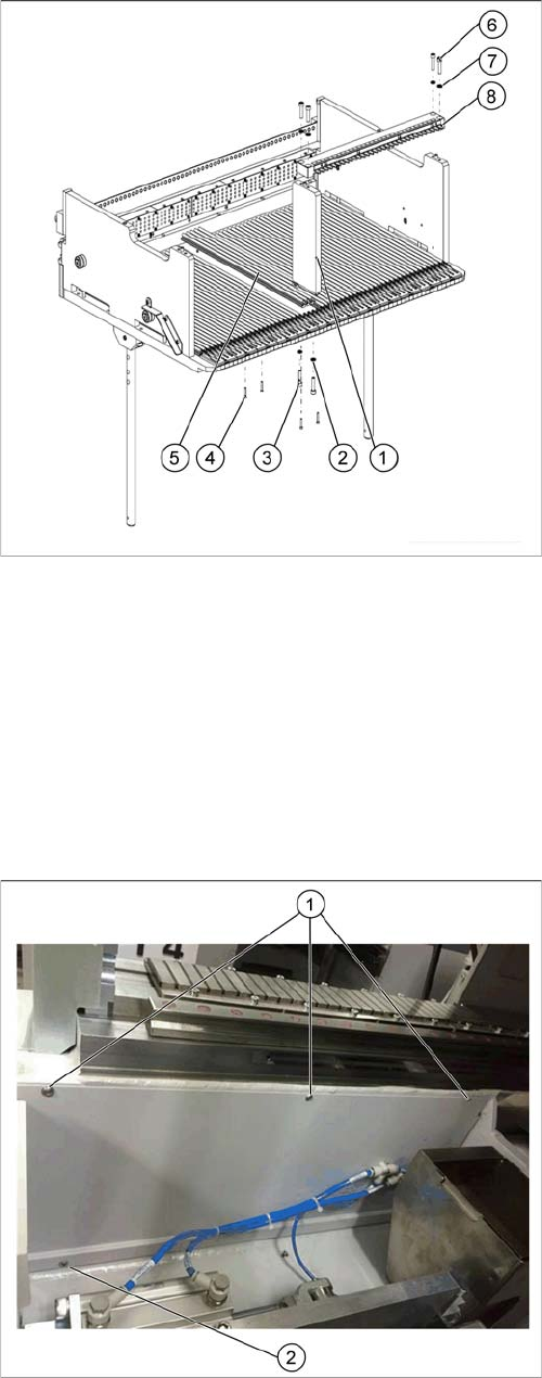
► Place the locking bar mount (1) on its installation lo-
cation.
► Fix the locking bar mount using the M6X25
screws (3) and washers (2) supplied.
► Place the guide profile reworked (5) on its installation
location.
► Fix the guide profile using the M3x18 screws (4) sup-
plied.
► Place the locking bar (8) on its installation location.
► Fix the locking bar using the M6X25 screws (6) and
the washers (7) supplied.
► Remove the three screws (1) from the side cover.
► Loosen the screws at the bottom of the side cover (2)
(the second screw is located behind the reject bin).
Setting up and Commissioning
Preparatory Work
User Manual JTF-MW on SIPLACE E 31
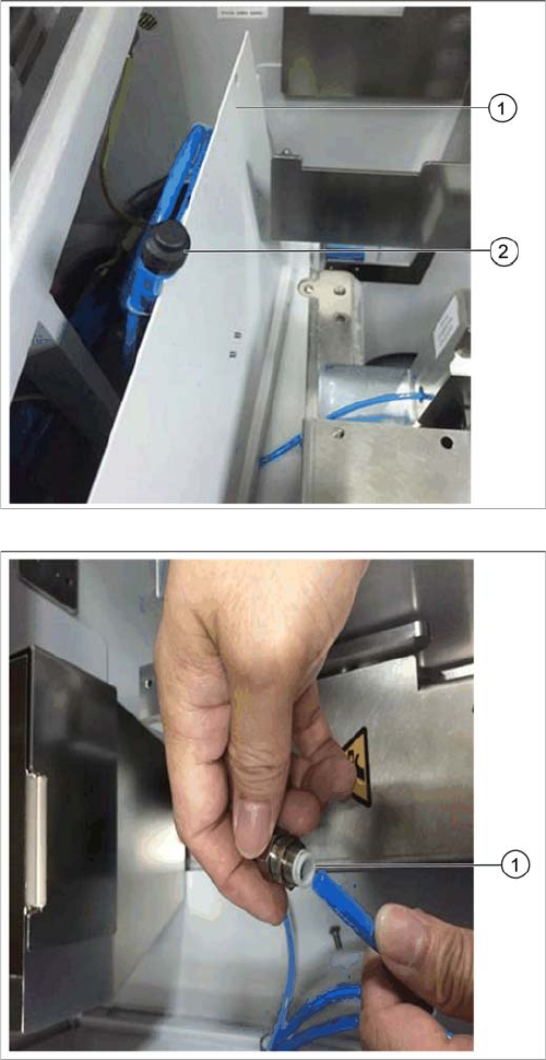
► Open the side cover (1).
► Locate the plug at the end of pneumatic tube (2).
► Replace the plug by the coupling [03117595-xx] (1)
from the retrofitting kit [03120613-xx].