00197961-01_UM_JTF-MW_on_SIPLACE_E_en_FINAL - 第40页
Setting up and Commissioning Configuration of SIPLACE JTF-MW in SIPLACE Pro 40 User Manual JTF-MW on SIPLACE E The SIPLACE JTF-MW is automatica lly configured on the track tha t is permitt ed for the machine. This track …
Setting up and Commissioning
Configuration of SIPLACE JTF-MW in SIPLACE Pro
User Manual JTF-MW on SIPLACE E 39
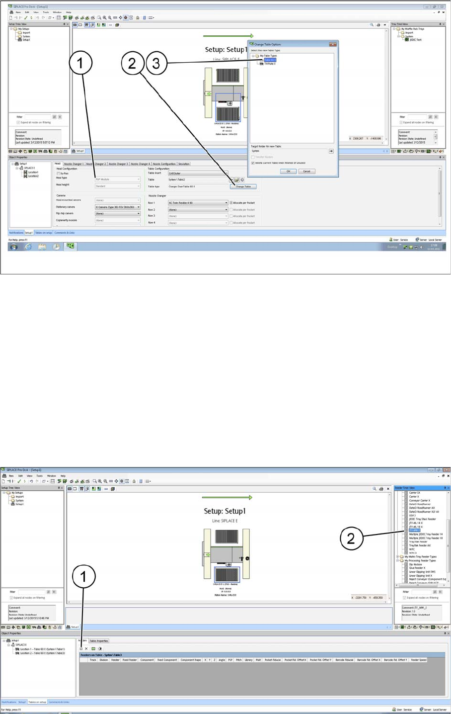
SIPLACE Pro - Example with table configurations
Head configuration: P&P Module (as example) (1)
Table configuration Change Table (2)
Confirm each selected table type (3) and confirm with OK.
After the relevant table type has been selected, the options in the Camera and Nozzle Changer fields
are automatically disabled. For design reasons, these configuration options are no longer available after
the table type has been selected.
All cameras and nozzle changer configurations that are selectable are displayed as active.
4.7.4.3
4.7.4.3 Configuring the SIPLACE JTF-MW on the Table
Configuring the SIPLACE JTF-MW on the Table
There are two ways for setting up the SIPLACE JTF-MW on the table:
Manually dragging the SIPLACE JTF-MW onto the table (2).
By selecting the Insert a new item into the collection menu option (1).
Setting up and Commissioning
Configuration of SIPLACE JTF-MW in SIPLACE Pro
40 User Manual JTF-MW on SIPLACE E
The SIPLACE JTF-MW is automatically configured on the track that is permitted for the machine.
This track cannot be changed.
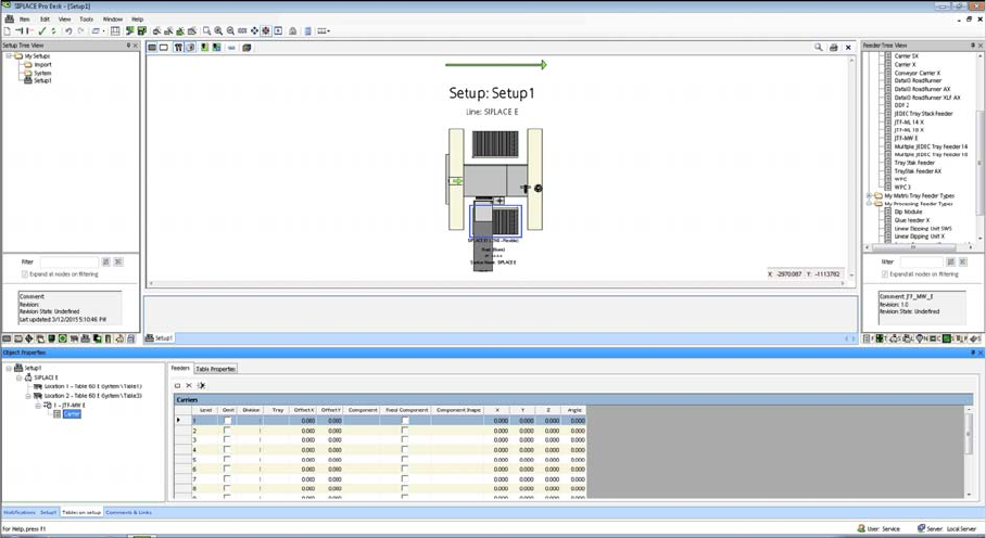
SIPLACE JTF-MW Carrier Level
For the Multiple JEDEC tray feeder 15, Carrier lists the number of trays (15) as well as their settings and
their component occupancy (per tray).
Tasks on the Machine
Powering up the Feeder
User Manual JTF-MW on SIPLACE E 41
5
5 Tasks on the Machine
Tasks on the Machine
This chapter describes how to operate the JTF-MW in the production process.
5.1
5.1 Powering up the Feeder
Powering up the Feeder
After connecting the feeder to the machine (see "4.6.2 Connecting the JTF-MW to the Machine" [➙35]),
the feeder initializes by driving the magazine upwards.
If no magazine is detected, the elevator drives down and switches to stands by.
If a magazine is detected, the first tray is positioned on the feeding level.
Now the feeder is ready to accept commands.
5.2
5.2 Controls and Displays on the Feeder Control Panel
Controls and Displays on the Feeder Control Panel
The diagram shows the control panel on the feeder.
The functions "Index, Inhibit and Elevator Down" are regulated by the controller.
The functions "Stop and Reset" are an electronic stopping function for the pneumatic system. If you
press the stop button, the pneumatic system immediately switches off and the motors will stop. The sta-
tus is read by the controller but not regulated by it.