M3plus_OperationManual_e.pdf - 第102页
3 - 37 4. Creating the component information 3 Creating the PCB data QFP A, B: Body Size X, Body Size Y Enter the correct dimensions (mm) including the leads, measured with a vernier caliper or mi- crometer. C: Body Size…
3 -36
3
Creating the PCB data
4. Creating the component information
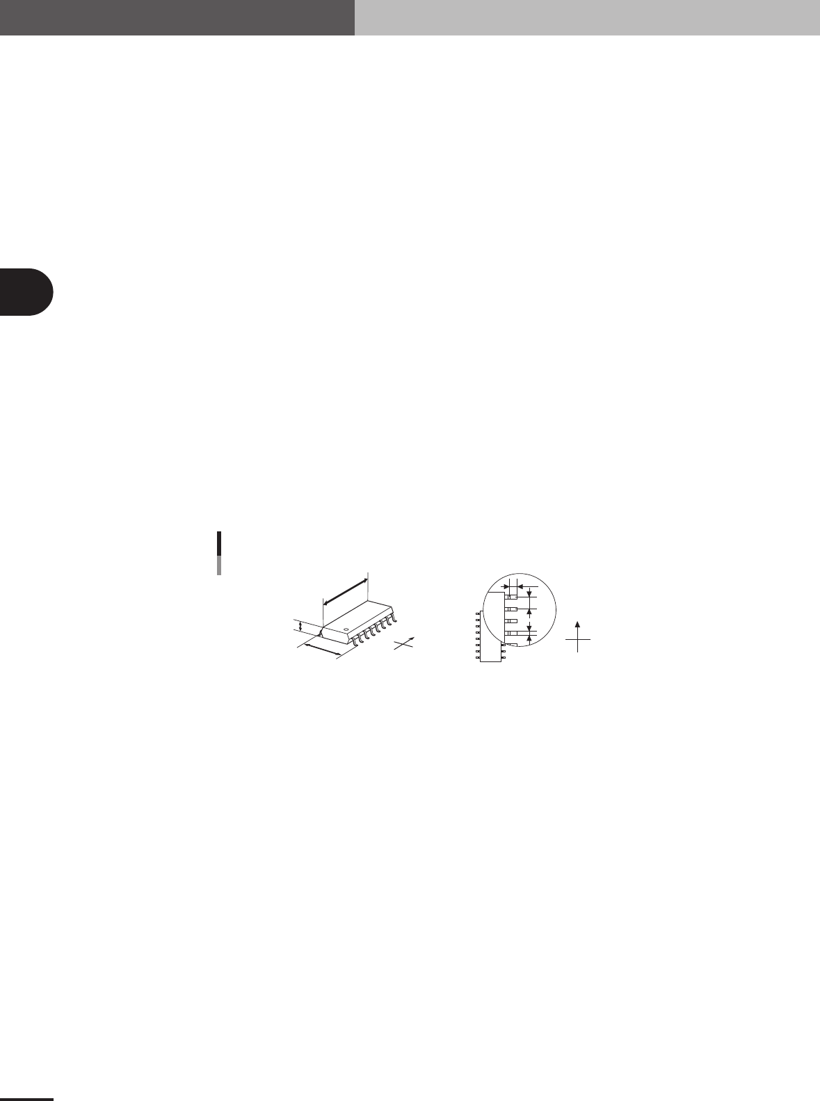
SOP
A, B: Body Size X, Body Size Y
Enter the correct dimensions (mm) including the leads, measured with a vernier caliper or mi-
crometer.
C: Body Size Z
Enter the correct thickness (mm) measured with a vernier caliper or micrometer.
D: Ruler Offset
Enter the distance in pixels from the end of the leads to an imaginary line used to measure the lead
width and pitch. Use the default setting in most cases.
E: Ruler Width
Enter the width of the imaginary line used to measure the lead width and pitch. Set this parameter
to "1 to 2" for components with a lead length shorter than 0.3mm, and to "2 to 3" for components
with a lead length longer than 0.3mm. Use the default setting in most cases.
F: Lead Number
Enter the number of leads existing in the E or W direction.
G: Lead Pitch
Enter the correct lead pitch (lead-to-lead spacing).
H: Lead Width
Enter the correct lead width
I: ReflectLL
Enter the projected length of leads which reflect light during recognition. Use the default setting in
most cases.
N
S
E
W
N
S
W
E
B
C
A
I
G
H
A : Body Size X
B : Body Size Y
C : Body Size Z
G : Lead Pitch
H : Lead Width
I : Reflect LL
Bottom view
Shape parameters for SOP
23421-5E-20
3 -37
4. Creating the component information
3
Creating the PCB data
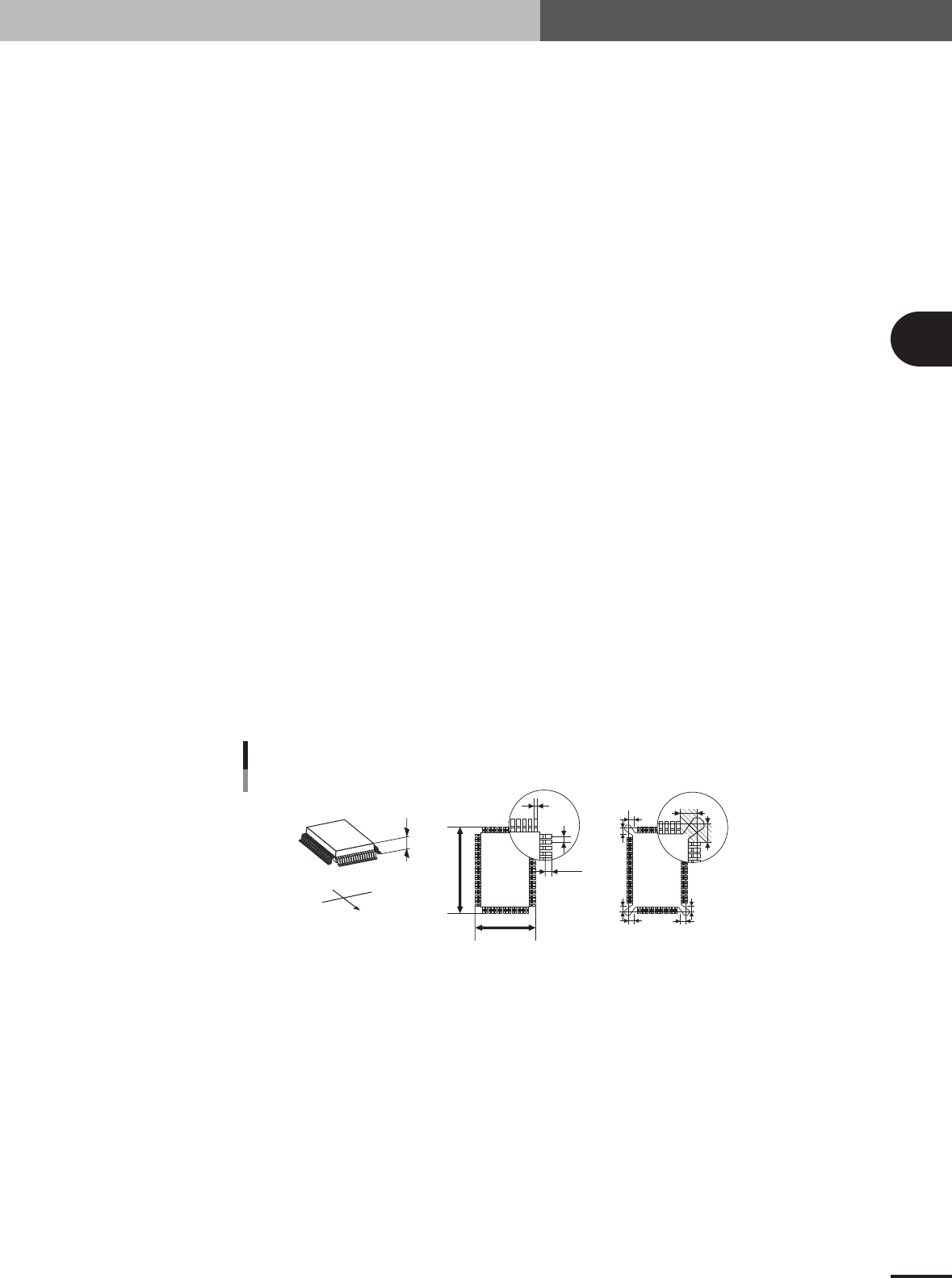
QFP
A, B: Body Size X, Body Size Y
Enter the correct dimensions (mm) including the leads, measured with a vernier caliper or mi-
crometer.
C: Body Size Z
Enter the correct thickness (mm) measured with a vernier caliper or micrometer.
D: Ruler Offset
Enter the distance in pixels from the end of the leads to an imaginary line used to measure the lead
width and pitch. Use the default setting in most cases.
E: Ruler Width
Enter the width of an imaginary line used to measure the lead width and pitch. Set this parameter
to "1 to 2" for components with a lead length shorter than 0.3mm, and to "2 to 3" for components
with a lead length longer than 0.3mm. Use the default setting in most cases.
F, G: Lead Number NE
Enter the number of leads existing in the N or E direction. For the component direction, see the
QFP pickup angle table.
H: Lead Pitch
Enter the correct lead pitch (lead-to-lead spacing).
I: Lead Width
Enter the correct lead width
J: ReflectLL
Enter the projected length of leads which reflect light during recognition. Use the default setting in
most cases.
K: Bumper Mask
This parameter is used for QFPs with bumpers. Enter the distance in millimeters from the cross
point of the imaginary lines so as to specify the area by which bumpers are masked and not
detected during component recognition. Set this parameter to a value between 0 and 10.0 in
0.25mm steps. Enter "0.00" for normal QFPs with no bumpers.
C
S
E
W
N
B
A
I
H
K
J
K
K
K
K
K
K
K
Bottom view
A : Body Size X
B : Body Size Y
C : Body Size Z
H : Lead Pitch
I : Lead Width
J : Reflect LL
K : Bumper Mask
Shape parameters for QFP
23422-5E-20
3 -38
3
Creating the PCB data
4. Creating the component information
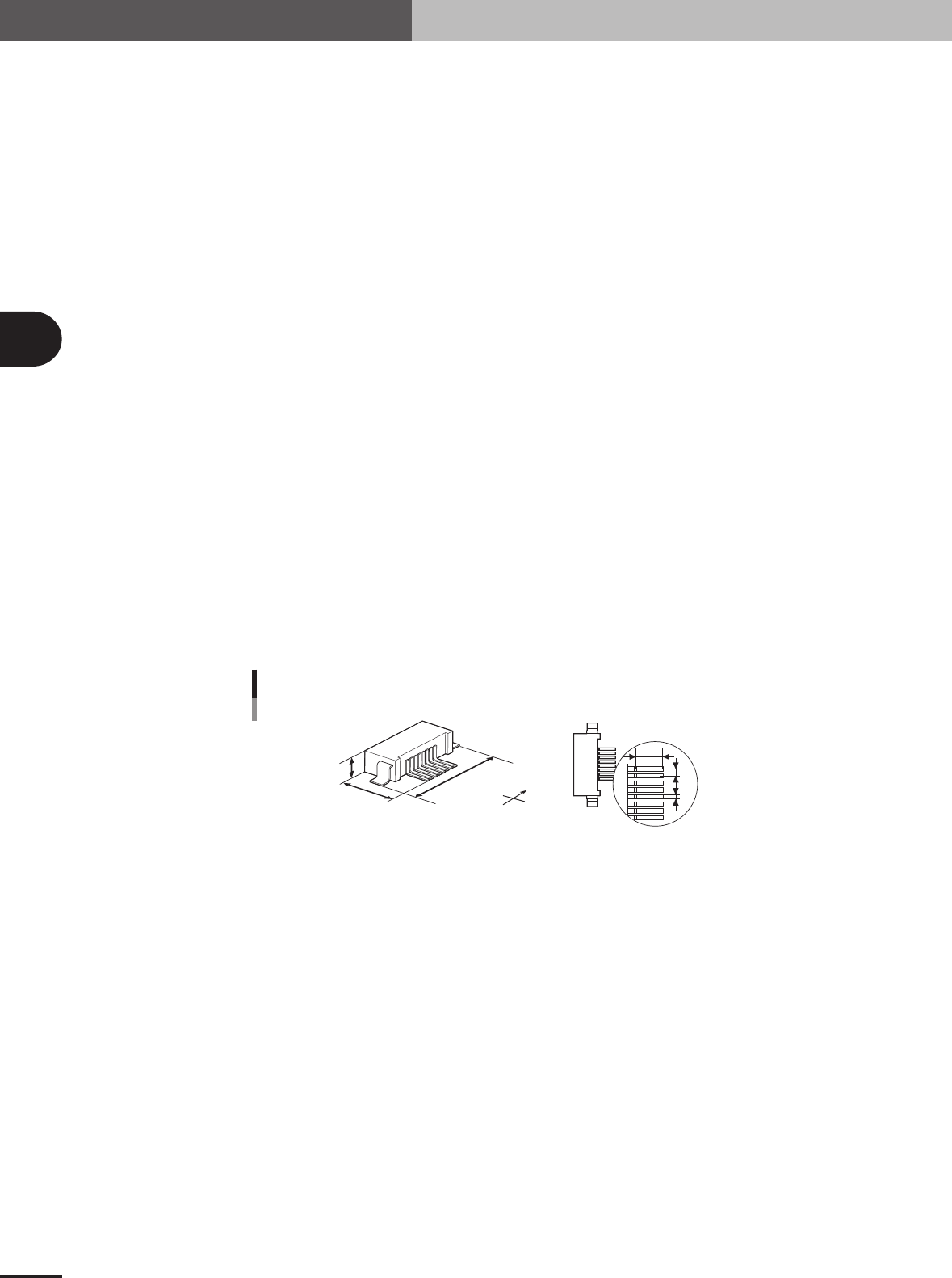
Connector E
A, B: Body Size X, Body Size Y
Enter the correct dimensions (mm) including the leads, measured with a vernier caliper or mi-
crometer.
C: Body Size Z
Enter the correct thickness (mm) measured with a vernier caliper or micrometer.
D, E, F: Cntr. Offset XYR
Enter the lead position offset (positional shift) relative to the center of the component.
G: Ruler Offset
Enter the distance in pixels from the end of the leads to an imaginary line used to measure the lead
width and pitch. Use the default setting in most cases.
H: Ruler Width
Enter the width of an imaginary line used to measure the lead width and pitch. Set this parameter
to "1 to 2" for components with a lead length shorter than 0.3mm, and to "2 to 3" for components
with a lead length longer than 0.3mm. Use the default setting in most cases.
I: LeadNumber
Enter the number of leads existing on one side.
J: Lead Pitch
Enter the correct lead pitch (lead-to-lead spacing).
K: Lead Width
Enter the correct lead width.
L: ReflectLL
Enter the projected length of leads which reflect light during recognition. Use the default setting in
most cases.
A : Body Size X
B : Body Size Y
C : Body Size Z
J : Lead Pitch
K : Lead Width
L : Reflect LL
Bottom view
S
N
W
E
B
C
A
L
J
K
Shape parameters for connector E
23426-5E-20