M3plus_OperationManual_e.pdf - 第106页
3 - 41 4. Creating the component information 3 Creating the PCB data M: Tray Height Enter the thickness (mm) of the tray. B A Component Tray Tray height (thickness) = A – B Tray height (thickness) 23445-5E-20 N, O: Waste…
3 -40
3
Creating the PCB data
4. Creating the component information
4.7 Tray parameters
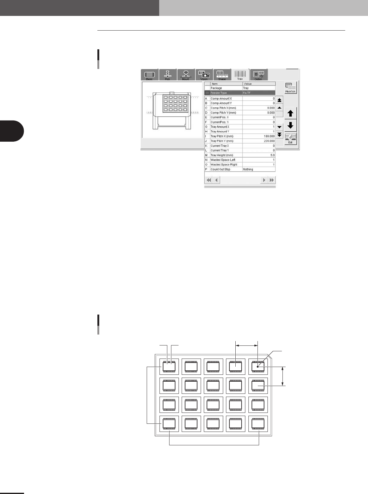
Open the Tray tab screen and set each parameter as follows.
Tray parameters
27444-5E-20
A, B: Comp. Amount XY
Enter the number of components in the XY directions on a tray. When using a tray shown in the
figure below, for example, set "5" to the Comp. Amount X and "4" to the Comp. Amount Y.
C, D: Comp Pitch XY
Enter the component pitch (center to center spacing) in millimeters in the XY directions.
E, F: Current Pos. XY
These parameters indicate which row and column on a tray the component is currently picked up
from. The row and column on a tray are counted from the tray origin (center of the component
placed closest to the back right corner of the tray as viewed from the front of the machine).
Normally, enter "1" in both the Current Pos. X and Current Pos. Y parameters when you have
created new component information.
Since these parameters automatically change as the components are picked up, so you can check
which row and column on the tray the components have been used from.
Tray reference position
Comp Amount / Current Pitch / Current Pos. settings
5,4
4,4 3,4 2,4 1,4
5,3 4,3 3,3 2,3 1,3
5,2 4,2 3,2 2,2 1,2
5,1 4,1 3,1 2,1 1,1
A
C
FE
D
B
23431-5E-20
3 -41
4. Creating the component information
3
Creating the PCB data
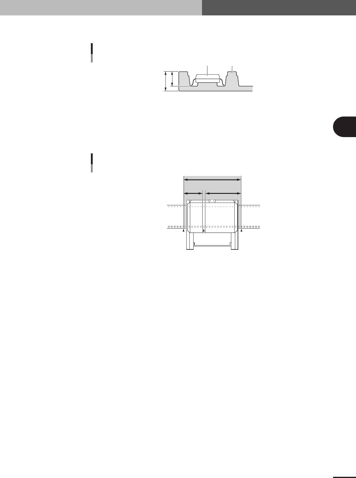
M: Tray Height
Enter the thickness (mm) of the tray.
B
A
Component
Tray
Tray height (thickness) = A – B
Tray height (thickness)
23445-5E-20
N, O: WastedSpace Left, Light
When a tray shuttle feeder (TSF1) is installed on the feeder plate, these parameters define the
feeder set positions where 8mm tape feeders cannot be attached to the feeder plate. These param-
eters should be set with the feeder set number as the reference that is specified in the "Feeder Set
No." field in the [Pick] tab grid.
109 135120
No feeders cannot be installed in this area
Feeder plate
MTF
WastedSpace (L) WastedSpace (R)
WastedSpace Left, Light
23437-5E-20
P: CountOutStop
When this parameter is set to "Exist", the machine automatically stops when the specified number
of components are used up. When set to "Nothing", the machine returns to the first position to
continue component pickup after the specified number of components are used up. Normally set
this parameter to "Nothing".
3 -42
3
Creating the PCB data
4. Creating the component information
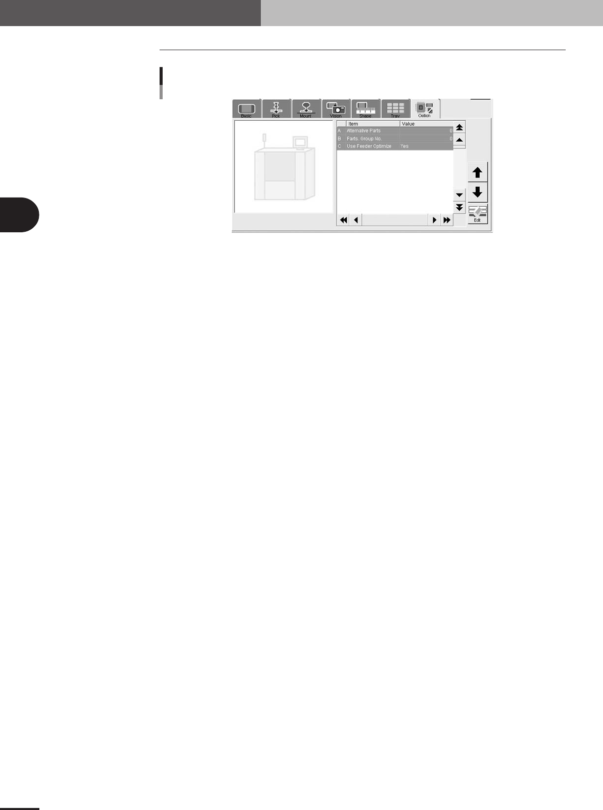
4.8 Option parameters
Option parameters
27418-5E-20
A: Alternative Parts
This parameter specifies an alternative component number which can be used if the current
component runs out. When not needed to specify any alternative component, leave it at "0". (For
details on alternative components, see "2.1" in chapter 4.)
B: Parts Group No.
When a nozzle lowers to mount a low-profile component after tall components have been mounted
on the PCB, the neighboring nozzles may interfere with those tall components. To avoid this,
components can be grouped by height so that they are mounted in the desired order (0 to 99). When
no mounting order is needed, set this parameter to "0".
C: Use Feeder Optimize
Set to "Yes" when you want to change the feeder set positions according to results obtained with
the Optimizer function. (See "3. Optimizing the data" in chapter 5.) Set to "No" if you do not want
to change the feeder set positions.