M3plus_OperationManual_e.pdf - 第108页
3 - 43 4. Creating the component information 3 Creating the PCB data 4.9 Parts Adjust mode The Parts Adjust mode allows you to check whether the parameter settings are appropri- ate. While performing the vision test, you…
3 -42
3
Creating the PCB data
4. Creating the component information
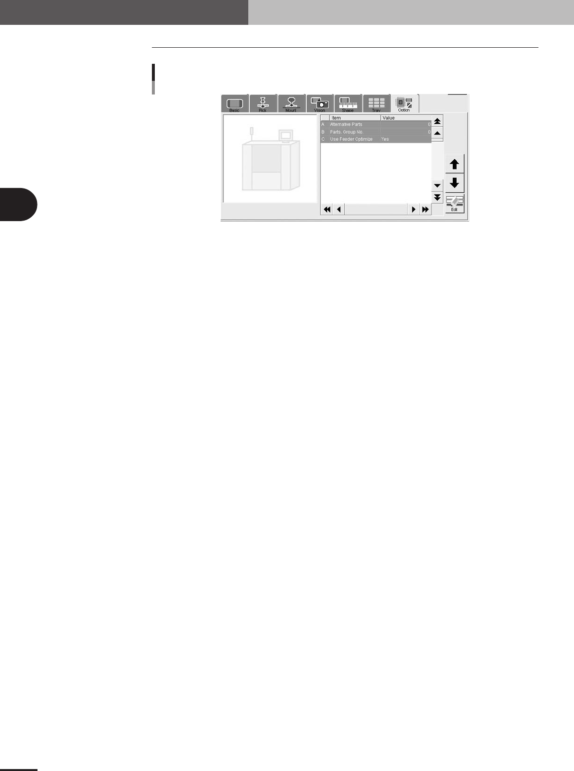
4.8 Option parameters
Option parameters
27418-5E-20
A: Alternative Parts
This parameter specifies an alternative component number which can be used if the current
component runs out. When not needed to specify any alternative component, leave it at "0". (For
details on alternative components, see "2.1" in chapter 4.)
B: Parts Group No.
When a nozzle lowers to mount a low-profile component after tall components have been mounted
on the PCB, the neighboring nozzles may interfere with those tall components. To avoid this,
components can be grouped by height so that they are mounted in the desired order (0 to 99). When
no mounting order is needed, set this parameter to "0".
C: Use Feeder Optimize
Set to "Yes" when you want to change the feeder set positions according to results obtained with
the Optimizer function. (See "3. Optimizing the data" in chapter 5.) Set to "No" if you do not want
to change the feeder set positions.
3 -43
4. Creating the component information
3
Creating the PCB data
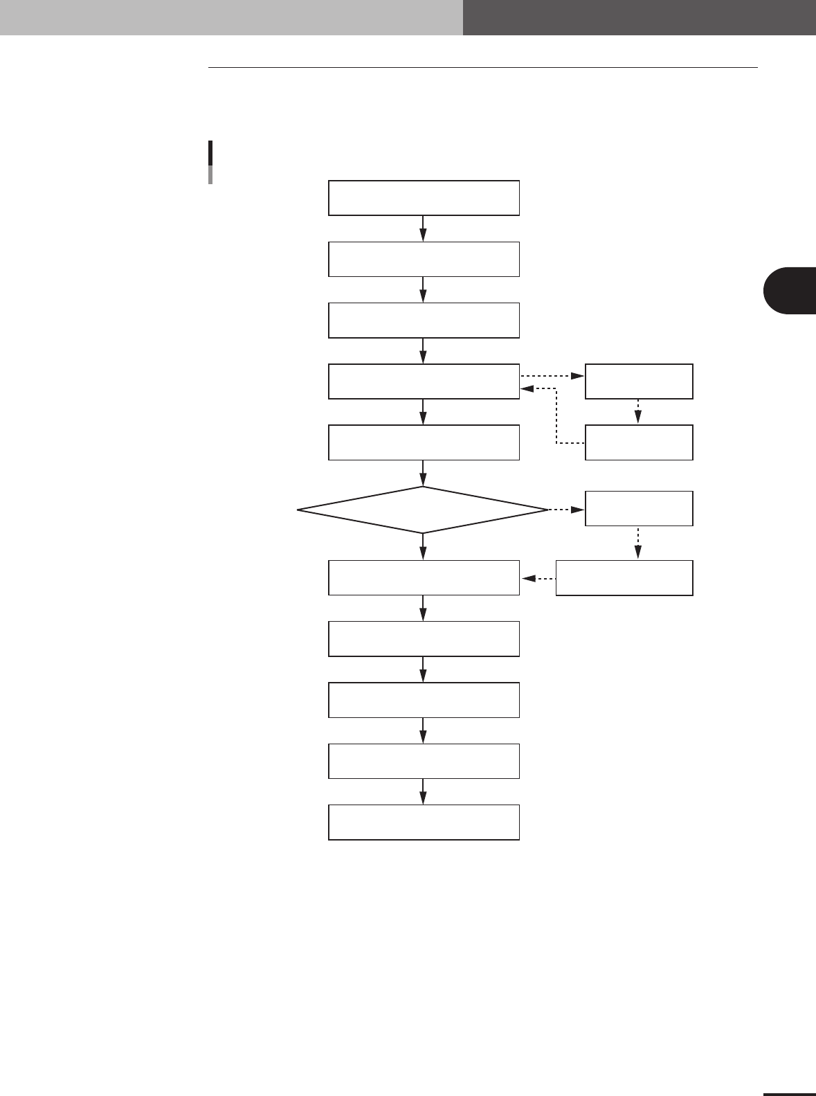
4.9 Parts Adjust mode
The Parts Adjust mode allows you to check whether the parameter settings are appropri-
ate. While performing the vision test, you can also find and determine an optimum value
for parameters which have not yet been set.
OK
NG
Te ach component (Single camera)
Typical flow chart in Parts Adjust mode
Select component data
Open Parts Adjust screen
Set feeder position
Press [Pick Up] button
Press [Test] button
Check head & nozzle
to be used
Check pickup/mount
vacuum levels
Press [Draw Shape] button
Press [Find Best] button
Press [Test] button
No error
Discard component
Quit Parts Adjust mode
Error occurred
23427-5E-20
3 -44
3
Creating the PCB data
4. Creating the component information
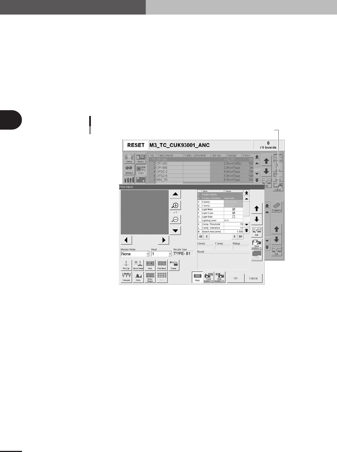
4.9.1 Parts Adjust mode
1
Set up the component feeder.
Install the feeder loaded with components you want to check. Be sure that the feeder
set position matches the number previously set for " Feeder Set No." of the Pick
parameters. If the Feeder Set No. has not yet been determined, you can specify it on
the Parts Adjust screen, so install the feeder at a position you can easily access.
2
Select the component data.
On the Component information screen, line up the cursor with the component data
you want to check.
3
Press the [Adjust] button to enter the Parts Adjust mode.
The Parts Adjust window appears as shown below.
Press the [Adjust] button to open the Parts Adjust window.
Parts Adjust screen
27423-5E-20