M3plus_OperationManual_e.pdf - 第110页
3 - 45 4. Creating the component information 3 Creating the PCB data 4 Enter the feeder set number. Enter this parameter only for components whose feeder position is unspecified. Move the cursor to "Feeder Set No.&q…
3 -44
3
Creating the PCB data
4. Creating the component information
4.9.1 Parts Adjust mode
1
Set up the component feeder.
Install the feeder loaded with components you want to check. Be sure that the feeder
set position matches the number previously set for " Feeder Set No." of the Pick
parameters. If the Feeder Set No. has not yet been determined, you can specify it on
the Parts Adjust screen, so install the feeder at a position you can easily access.
2
Select the component data.
On the Component information screen, line up the cursor with the component data
you want to check.
3
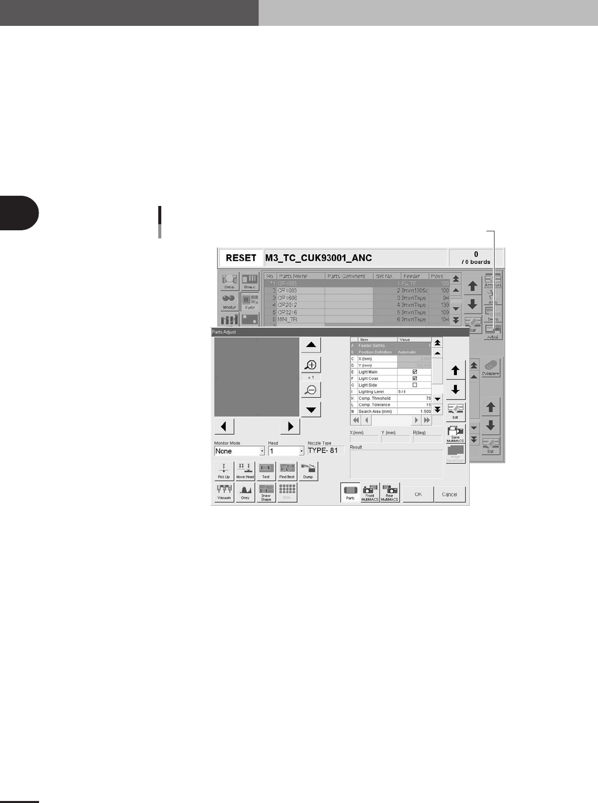
Press the [Adjust] button to enter the Parts Adjust mode.
The Parts Adjust window appears as shown below.
Press the [Adjust] button to open the Parts Adjust window.
Parts Adjust screen
27423-5E-20
3 -45
4. Creating the component information
3
Creating the PCB data
4
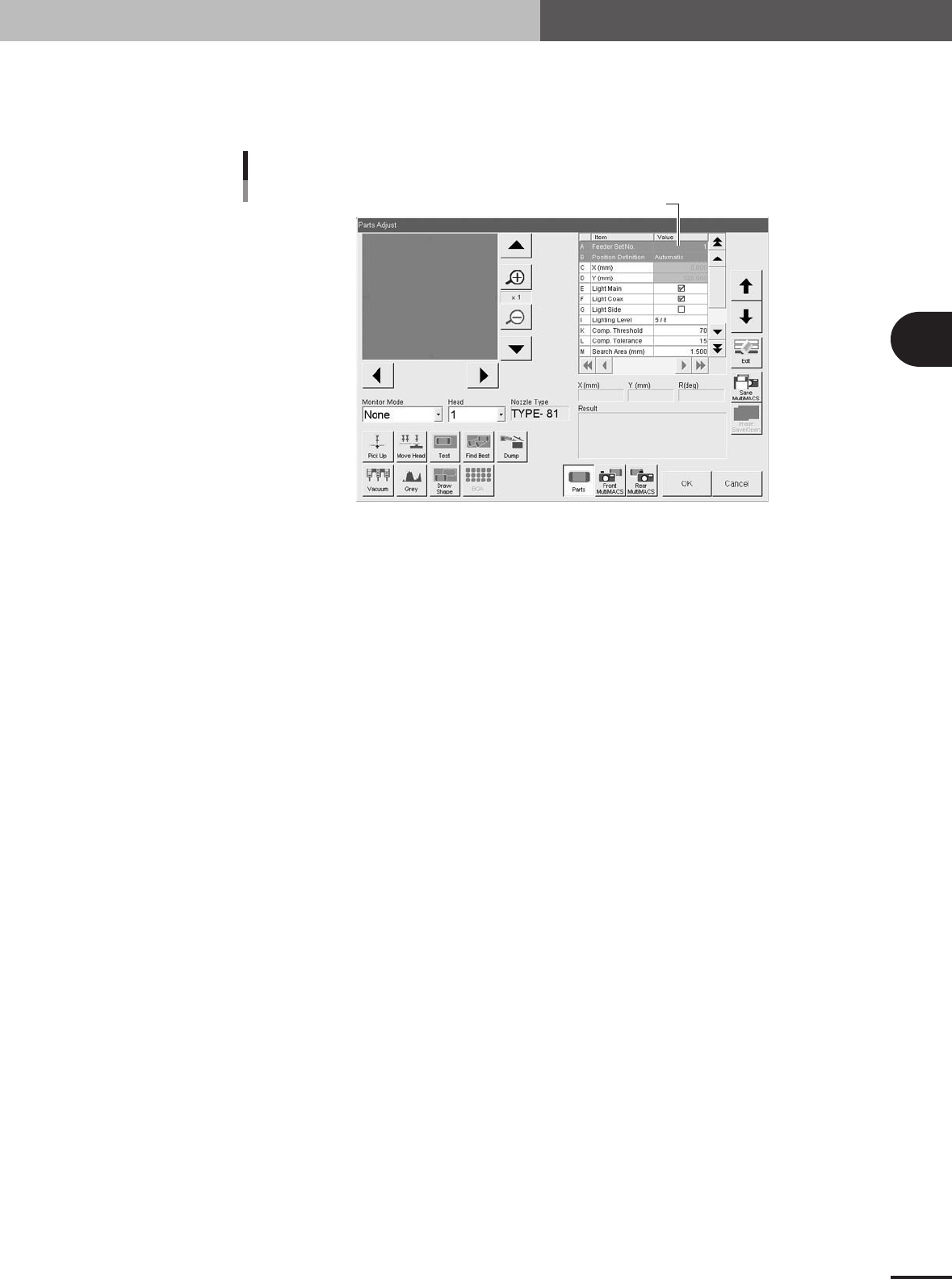
Enter the feeder set number.
Enter this parameter only for components whose feeder position is unspecified. Move
the cursor to "Feeder Set No." in parameter list, then enter the number of the feeder
plate position at which the feeder is installed.
Step 4: Set feeder position
Feeder position input screen
27426-5E-2A
5
Check the head and nozzle to be used.
The head number and nozzle type to be used are shown on the screen. To change
the head number, select it from the Head dropdown list. If you want to change the
nozzle type, exit the Parts Adjust mode and then change the "Required Nozzle"
setting on the Basic tab screen.
6
Perform component pickup.
Press the [Pick Up] button on the Parts Adjust screen. The head assembly moves to
pick up a component.
3 -46
3
Creating the PCB data
4. Creating the component information
7
Check and adjust the reference pickup/mount vacuum levels.
To check the reference vacuum levels used to determine whether or not a component
is being picked up by a nozzle, follow these steps.
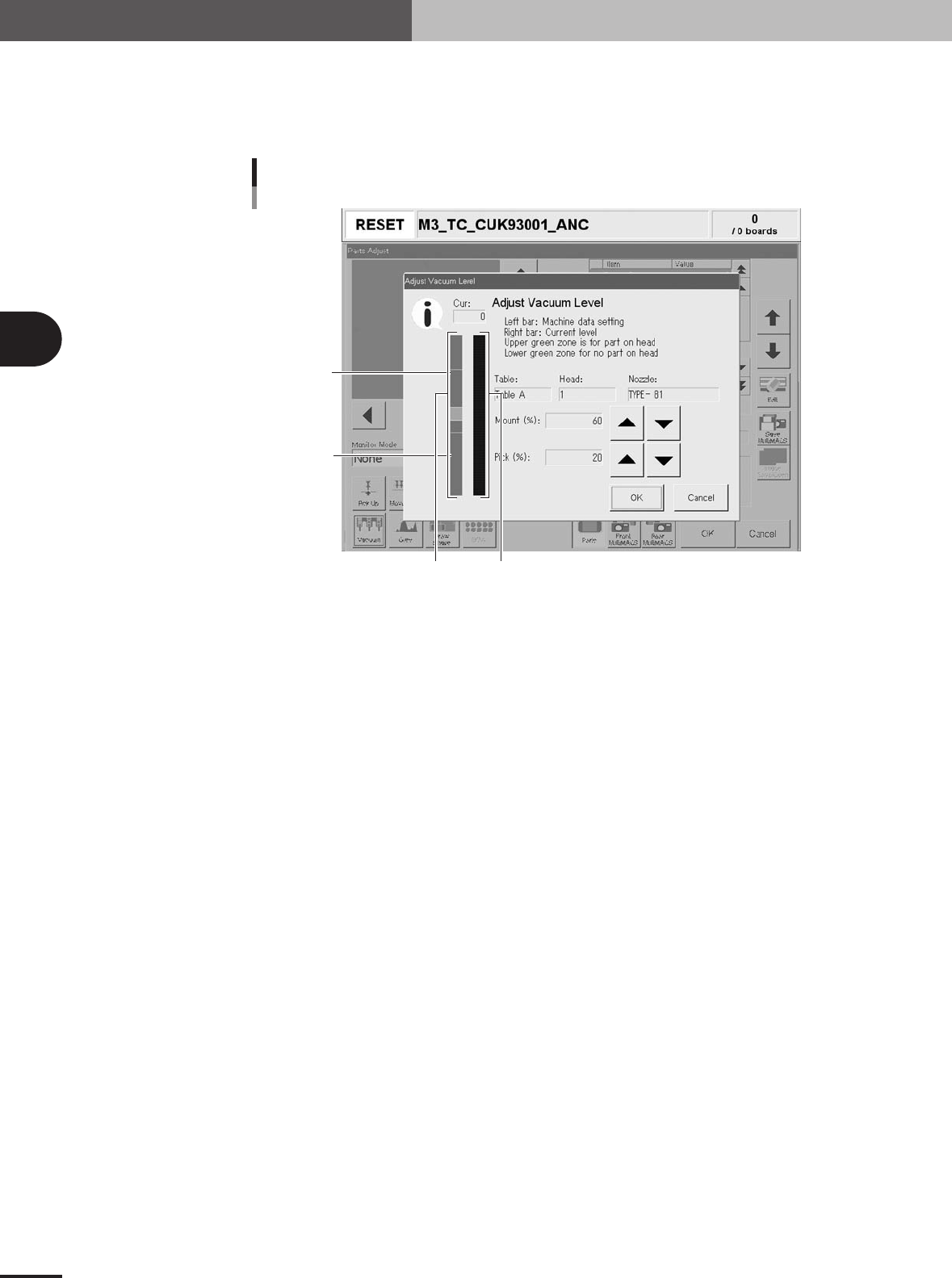
1.Press the [Vacuum] button to open the Adjust Vacuum Level window.
C
D
B
A
A: Data bar
Shows the reference pickup and mount vacuum level settings.
B: Level bar
Shows the actual vacuum level currently being measured.
C: Upper green zone
Represents the reference pickup vacuum level setting when a component is picked up by
the nozzle.
D: Lower green zone
Represents the reference mount vacuum level setting when no component is picked up by
the nozzle.
Adjust Vacuum Level window
27430-5E-20
2.Check the reference mount vacuum level.
Check that the Level bar overlaps with the upper green zone on the Data bar. If
not, increase the reference mount vacuum level (Mount %) with the UP arrow
button.
3.Check the reference pickup vacuum level.
Press the emergency stop button, then remove by hand the component being
picked up. Now check that the Level bar is within the lower green zone on the Data
bar. If the Level bar exceeds the green area and overlaps with the center pink zone,
adjust the reference pickup vacuum level (Pick %) with the UP arrow button. After
having adjusted it, cancel the emergency stop button and press the [READY] button.
4.Press the [Pick Up] button to perform component pickup again.
8
Press the [Test] button to perform the vision test.
Perform this test several times. If no error is detected, each parameter is appropriate
so advance to the next step. If an error occurs during this test, make adjustments with
the procedure below.