M3plus_OperationManual_e.pdf - 第113页
3 - 48 3 Creating the PCB data 4. Creating the component information 9 Discard the component. To discard the component at the dumping position, press the [Dump] button. If you do not want to dump the component, follow th…
3 -47
4. Creating the component information
3
Creating the PCB data
• If an error occurs, perform the following operation.
n
NOTE
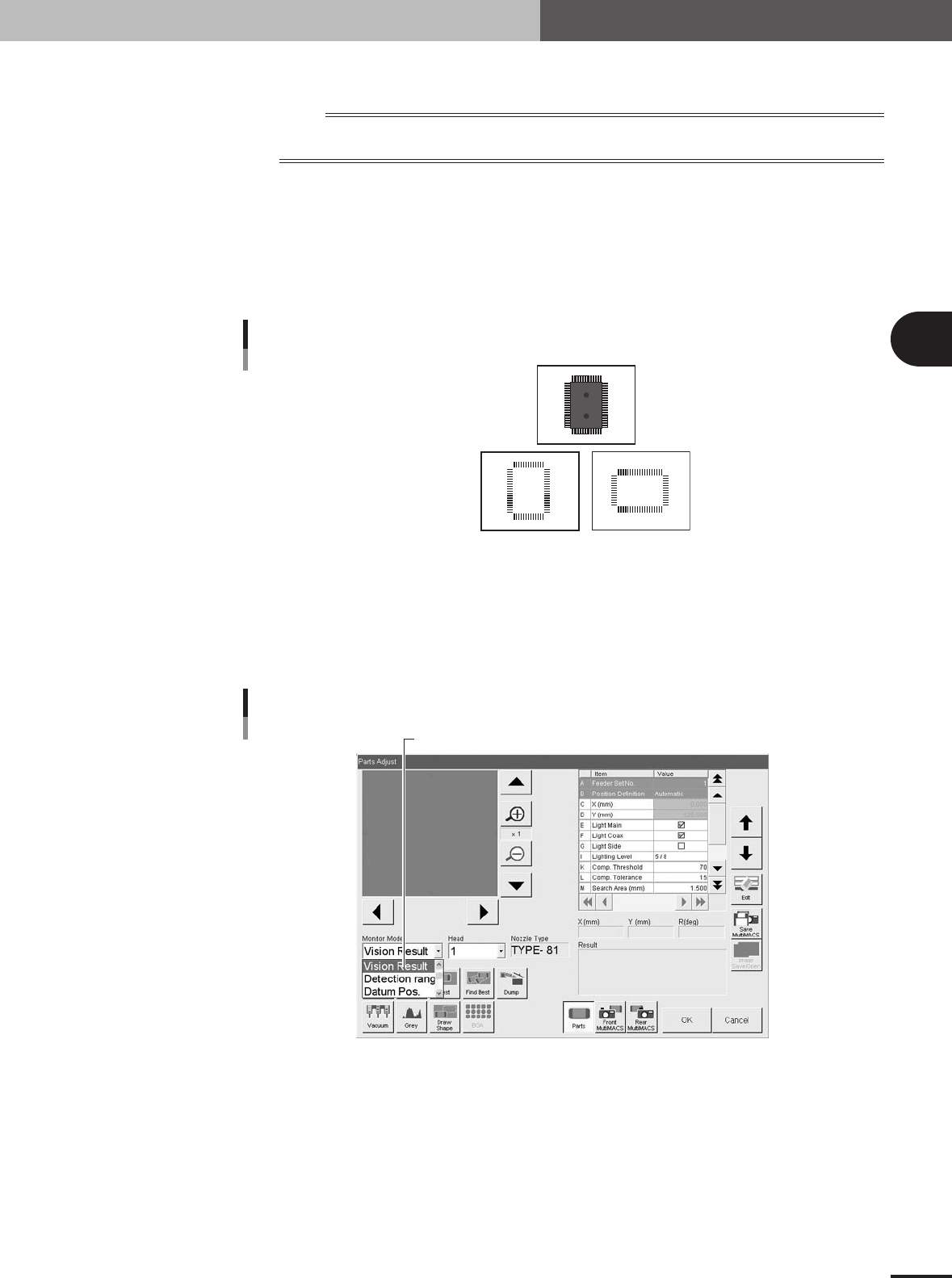
To check the outline definition of a component recognized with a multi-vision camera, use the image recognized
when the component passes over the camera from the front left to rear right as the reference.
1.After checking the direction of the component displayed on the vision monitor,
press the [Draw Shape] button.
An outline of the component is displayed on the vision monitor, based on the
setting data defined in the component information, so confirm whether it matches
the component image you have checked with the vision test. If the direction does
not match, exit the Parts Adjust mode once, and then correct the "Pick Angle deg"
setting on the Pick tab screen.
9632 Z00
OK NG
Component image and outline definition
Component image
taken by vision test
Component outline
displayed with the
[Draw Shape] button
23428-5E-20
2.Check the parameters on the Shape tab screen.
To make this check, set the Monitor Mode to "Vision Result" and then perform the
vision test again. The recognition results will be displayed on the vision monitor.
Then check if the parameter settings on the Shape tab screen such as "Body Size"
and "Lead Number" match the results obtained. Correct the settings as necessary.
Set "Monitor Mode" to "Vision Result".
Monitor Mode setting
27431-5E-20
3.Press the [Find Best] button on the Parts Adjust screen.
The machine automatically finds and enters the optimum values for the component
parameters.
4.Press the [Test] button to perform the vision test again.
Repeat this test several times. If there is no error, the adjustment is complete.
Return the Monitor Mode setting to "None".

3 -48
3
Creating the PCB data
4. Creating the component information
9
Discard the component.
To discard the component at the dumping position, press the [Dump] button. If you
do not want to dump the component, follow the procedure below.
1.Press the [Pick Up] button.
2.When the head stops completely at the component pickup position, press the
emergency stop button and remove the component by hand from the nozzle.
3.Press the [Dump] button to stop vacuum generation.
0
Quit the Parts Adjust mode.
Press the [OK] button on the Parts Adjust screen to quit the Parts Adjust mode.
e
3 -49
4. Creating the component information
3
Creating the PCB data
4.10 Using component feeders other than tape feeders
4.10.1 Setting the stick feeder component data
When using stick feeder components (except for multi-stick feeders), make the following
settings in the component information.
1
Set the stick feeder on the feeder plate.
Install the stick feeder on the feeder plate, at a position that meets the following two
conditions.
1.Within the working range of the moving camera
The moving camera is used for teaching of the component pickup point.
2.On the front feeder plate
The component information is specified based on the component supply from the
front feeder plate.
2
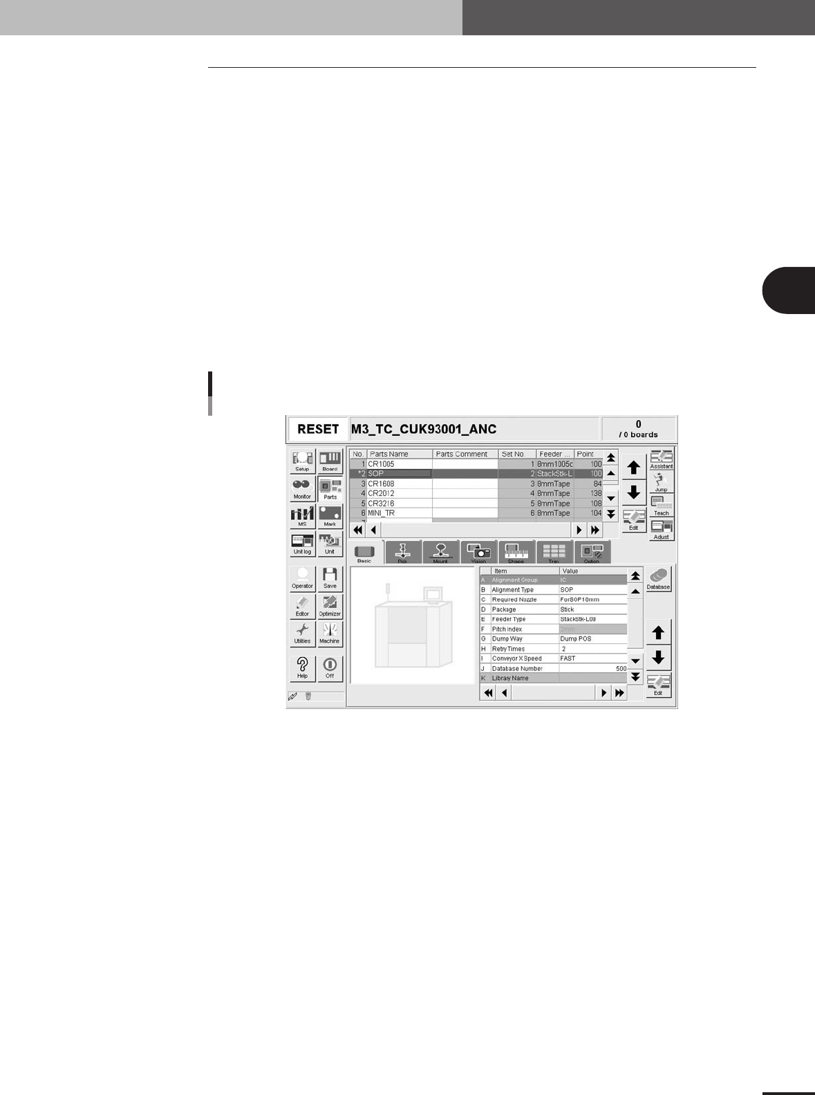
Select the component data.
Open the [Parts] screen, and line up the cursor with the data line of the component
which is supplied by the stick feeder.
Selecting the component
27432-5E-20
3
Set "Package" of the Basic parameters to "Stick".
On the [Basic] tab screen, set the "Package" parameter item to "Stick".