M3plus_OperationManual_e.pdf - 第117页
3 - 52 3 Creating the PCB data 4. Creating the component information 8 Set the data optimization. Open the Option tab screen, and set "Use Feeder Optimize" to "Yes" or "No". Set to "Yes…
3 -51
4. Creating the component information
3
Creating the PCB data
6
Set "Position Definition" of the Pick parameters.
Set this parameter to "Automatic" when using a stick feeder.
n
NOTE
The "Position Definition" parameter specifies the method for obtaining the coordinates of a component pickup
position.
When "Automatic" is selected, the machine automatically calculates the pickup position based on the feeder plate
reference position. Select this setting when using components whose pickup position is independent of the
component size, such as tape feeders.
7
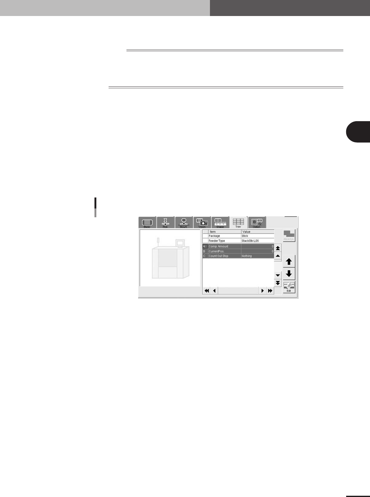
Set the Tray parameters.
Open the Tray tab screen and set each parameter as follows.
• Comp. Amount:
Enter the number of components loaded into a single stick.
• Current Pos.:
This shows the number of components which have been used from the stick. Use
the initial setting value.
• CountOut Stop:
Normally, set this parameter to "Nothing". If this is set to "Exist", the machine will
automatically stop when the number of components set in the Comp Amount
parameter have been used up.
Tray parameter setting
27437-5E-20
3 -52
3
Creating the PCB data
4. Creating the component information
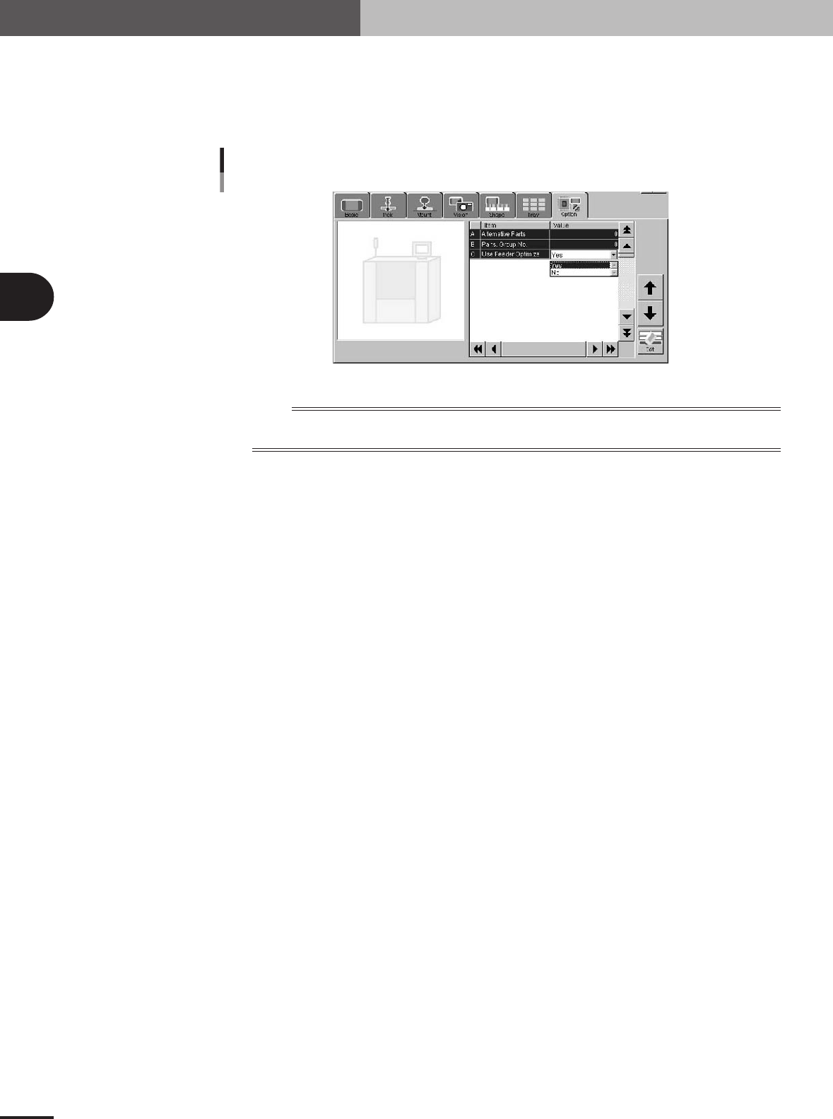
8
Set the data optimization.
Open the Option tab screen, and set "Use Feeder Optimize" to "Yes" or "No".
Set to "Yes" when optimizing the feeder set positions after creating the PCB data.
Set to "No" when not optimizing the feeder set positions after creating the PCB data
(to set the feeder should at a particular position).
"Use Feeder Optimize" parameter setting
27438-5E-20
n
NOTE
When the stick feeder needs to be installed at a particular position, you cannot make off-line settings. Be sure to
use teaching to enter the correct pickup point.
3 -53
4. Creating the component information
3
Creating the PCB data
4.10.2 Tray shuttle feeder
When supplying components from a tray shuttle feeder (called "TSF1"), make the follow-
ing settings.
1
Set the TSF1 on the feeder plate.
Install the TSF1 on the feeder plate and then set tray components.
n
NOTE
The TSF1 can be installed in position 1 or position 2, each of which occupies the following width on the feeder
plate.
Position 1: Occupies a width from feeder set positions 1 to 7.
Position 2: Occupies a width from feeder set positions 8 to 14.
c
CAUTION
It is not possible to install the TSF1 in position 2 only. For details on how to handle the TSF1
and set tray components, refer to the TSF1 manual at the end of this manual.
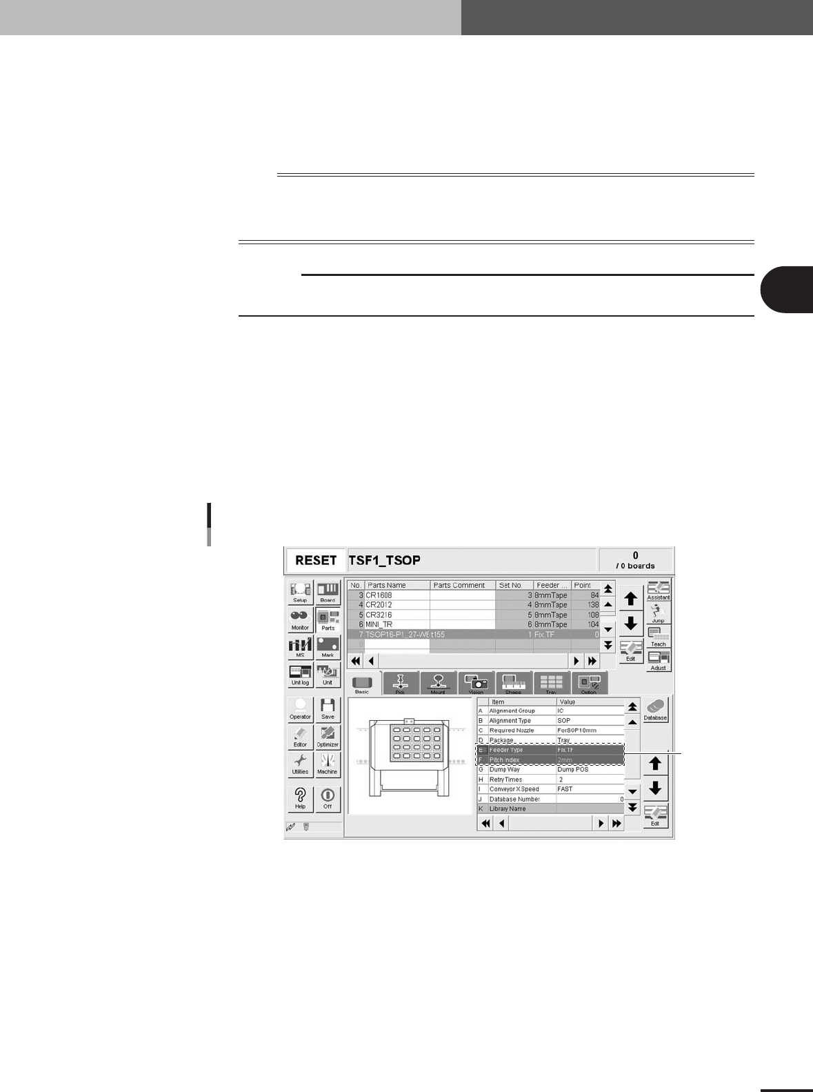
2
Select the component and set the alignment type.
Open the [Parts] screen and line up the cursor with the component that should be
supplied from the TSF1. Set "Alignment Group", "Alignment Type" and "Required
Nozzle" in the [Basic] tab grid.
3
Set "Package" of the Basic parameters.
In the [Basic] tab grid, set "Tray" to "Package".
4
Set "Feeder Type" of the Basic parameters.
In the [Basic] tab grid, set "Fix. TF" to "Feeder Type".
Basic parameters
Set these
parameters.
27442-5E-20