M3plus_OperationManual_e.pdf - 第120页
3 - 55 4. Creating the component information 3 Creating the PCB data 4. Move the head assembly by hand to a point at which a component on the tray is viewed with the moving camera. n NOTE Components on the tray are not e…
3 -54
3
Creating the PCB data
4. Creating the component information
5
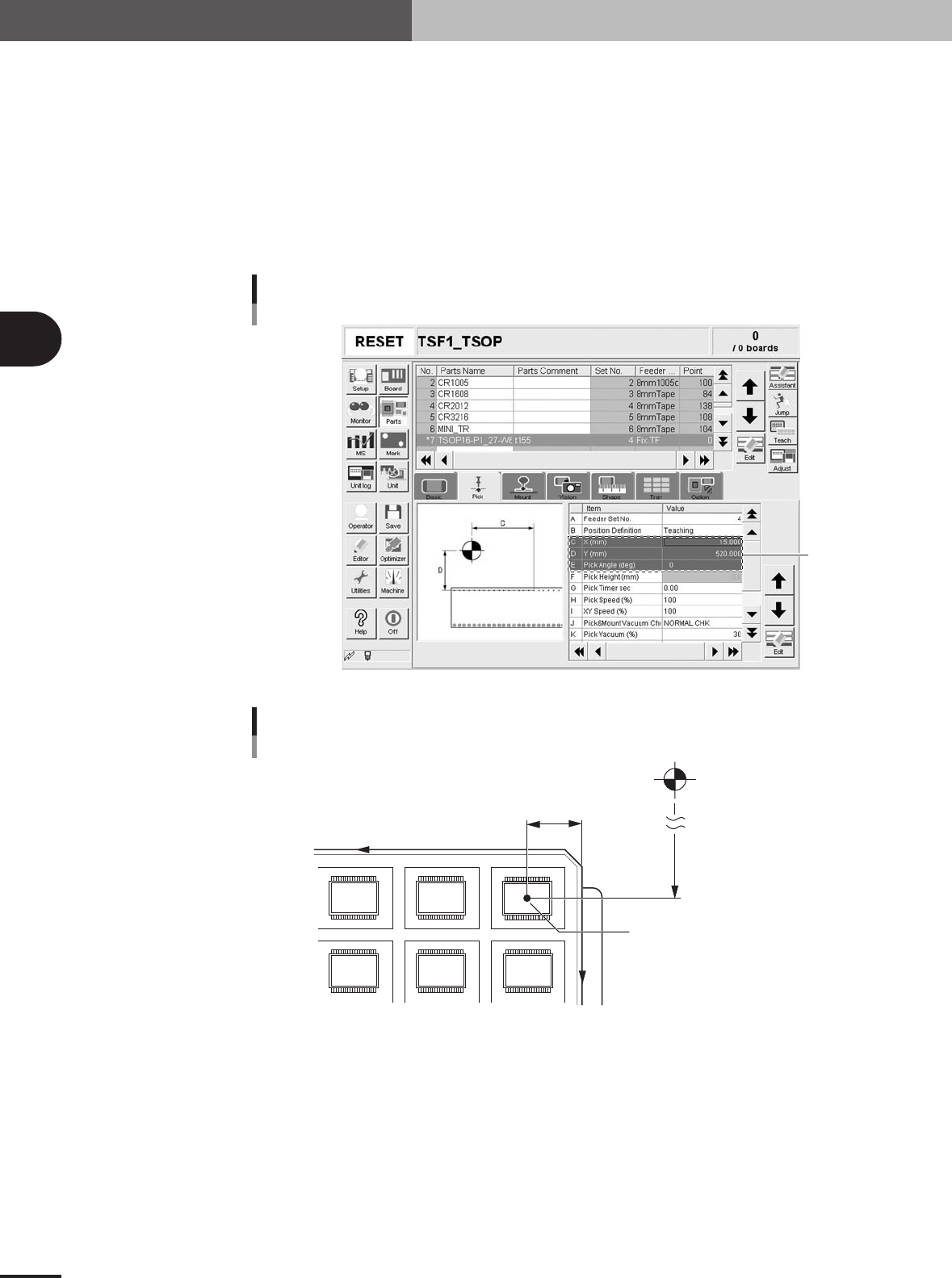
Set "Feeder Set No." of the Pick parameters.
Open the [Pick] tab and set "4" to "Feeder Set No." when you have installed the
TSF1 in position 1 or set "11" when you have installed the TSF1 in position 2.
6
Set "Position Definition" of the Pick parameters.
In the [Pick] tab grid, set "Teaching" to "Position Definition".
7
Set "X (mm)" of the Pick parameters.
Measure the distance to the tray reference position from the tray origin with a vernier
caliper or measuring tape, and then enter it in the "X (mm)" field of the [Pick] tab
grid.
Pick parameters
Set these
parameters.
27443-5E-20
Pickup position
X
Y
Pickup position X mm
(Enter this value manually.)
Pickup position Y mm
(Enter this value by teaching.)
Tray reference position (1st pickup point)
Machine origin
23434-5E-20
8
Set "Y (mm)" of the Pick parameters.
Referring to the procedure below, perform teaching for the coordinates of the compo-
nent pickup position.
1.Press the [Teach] button to open the teach window.
2.Press the emergency stop button on the TSF1 and then open the upper safety cover.
3.Move the shuttle by hand to near the pickup position (where a component on the
tray is roughly aligned with the axis of the moving camera.)
e
3 -55
4. Creating the component information
3
Creating the PCB data
4.Move the head assembly by hand to a point at which a component on the tray is
viewed with the moving camera.
n
NOTE
Components on the tray are not exactly focused because of the camera structure. The image appears blurred as
shown below. Adjust the camera lighting levels as needed, to make it easier to view the teaching point.
5.Close the TSF1 and mounter safety covers, cancel the emergency stop button and
press the [READY] button.
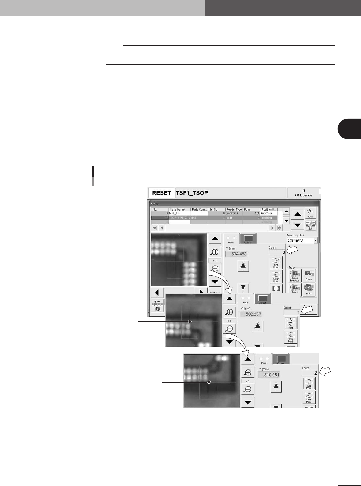
6.Press the [Click Move] button, place the mouse pointer at the component lead edge
on the N side (or S side), and click the mouse button. (When the component has
no leads, click at a component mold edge.)
7.When the camera has moved to the component lead edge, click the [Set Point]
button once. (The "Count" box in the teach window changes from "0" to "1".)
8.Move the camera by teaching to the opposite lead edge of the component.
9.When the camera has moved to the opposite lead edge, click the [Set Point] button
once.
Check that the "Count" box has changed from "1" to "2" and then click the
[Teach] button.
Setting the pickup position Y (mm)
First point
Second point
27320-5E-20
10.The above procedure automatically enters the pickup position (Y position only).
Close the teach window by pressing the [Close] button.
3 -56
3
Creating the PCB data
4. Creating the component information
11.Open the [Pick] tab and check that the Y position value is entered in the "Y (mm)"
field.
X (mm) and Y (mm) positions
27321-5E-20
n
NOTE
Clicking the [Teach] button does not automatically enter the "X (mm)" position. You must manually enter the "X
(mm)" position.
c
CAUTION
When using two TSF1 units installed in positions 1 and 2 on the feeder plate, two sets of
component data will be required even when picking up the same type of tray components from
the two TSF1, because the pickup position Y differs between positions 1 and 2. To create this
component data, always first install the TSF1 at the position actually used for production and
set tray components on theTSF1.
9
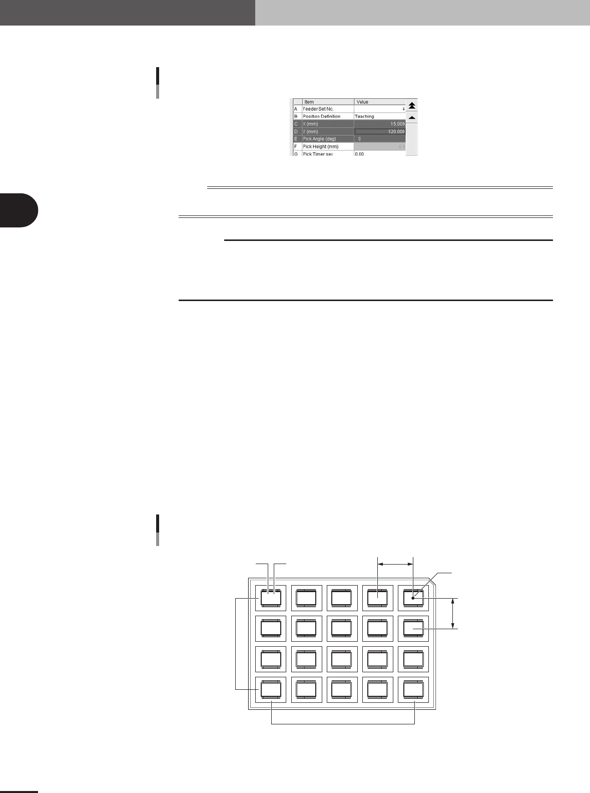
Set the tray parameters.
Open the [Tray] tab and set each parameter as follows.
A, B: Comp. Amount XY
Enter the number of components in the XY directions on a tray.
C, D: Comp Pitch XY
Enter the component pitch (center to center spacing) in millimeters in the XY directions on a tray.
E, F: Current Pos. XY
These parameters indicate which row and column on a tray the component is currently picked up
from. The row and column on a tray are counted from the tray reference position.
Normally, enter "1" in both the Current Pos. X and Current Pos. Y parameters when you have
created new component information. With these parameters set to "1", the machine starts picking
up a component from the tray reference position. Since these parameters automatically change as
the components are picked up, so you can check which row and column on the tray the components
have been used up to.
Tray reference position
Comp Amount / Current Pitch / Current Pos. settings
5,4
4,4 3,4 2,4 1,4
5,3 4,3 3,3 2,3 1,3
5,2 4,2 3,2 2,2 1,2
5,1 4,1 3,1 2,1 1,1
A
C
FE
D
B
23431-5E-20