M3plus_OperationManual_e.pdf - 第122页
3 - 57 4. Creating the component information 3 Creating the PCB data G, H: Tray Amount XY These parameters specify the number of trays set in the XY directions on the shuttle. For example in the figure below, enter "…
3 -56
3
Creating the PCB data
4. Creating the component information
11.Open the [Pick] tab and check that the Y position value is entered in the "Y (mm)"
field.
X (mm) and Y (mm) positions
27321-5E-20
n
NOTE
Clicking the [Teach] button does not automatically enter the "X (mm)" position. You must manually enter the "X
(mm)" position.
c
CAUTION
When using two TSF1 units installed in positions 1 and 2 on the feeder plate, two sets of
component data will be required even when picking up the same type of tray components from
the two TSF1, because the pickup position Y differs between positions 1 and 2. To create this
component data, always first install the TSF1 at the position actually used for production and
set tray components on theTSF1.
9
Set the tray parameters.
Open the [Tray] tab and set each parameter as follows.
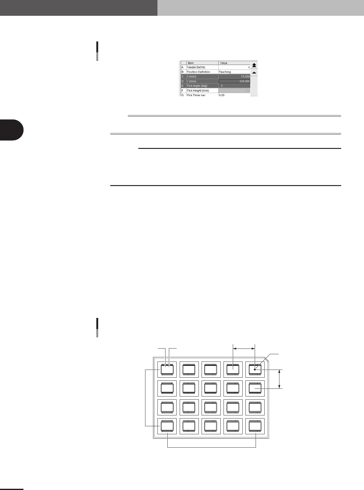
A, B: Comp. Amount XY
Enter the number of components in the XY directions on a tray.
C, D: Comp Pitch XY
Enter the component pitch (center to center spacing) in millimeters in the XY directions on a tray.
E, F: Current Pos. XY
These parameters indicate which row and column on a tray the component is currently picked up
from. The row and column on a tray are counted from the tray reference position.
Normally, enter "1" in both the Current Pos. X and Current Pos. Y parameters when you have
created new component information. With these parameters set to "1", the machine starts picking
up a component from the tray reference position. Since these parameters automatically change as
the components are picked up, so you can check which row and column on the tray the components
have been used up to.
Tray reference position
Comp Amount / Current Pitch / Current Pos. settings
5,4
4,4 3,4 2,4 1,4
5,3 4,3 3,3 2,3 1,3
5,2 4,2 3,2 2,2 1,2
5,1 4,1 3,1 2,1 1,1
A
C
FE
D
B
23431-5E-20
3 -57
4. Creating the component information
3
Creating the PCB data
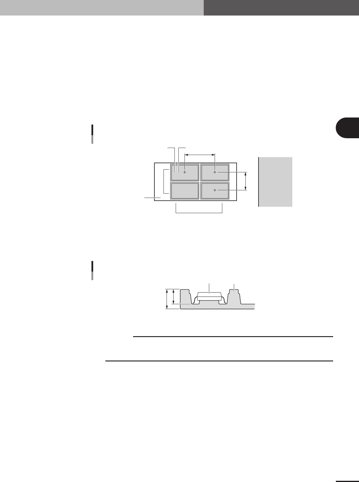
G, H: Tray Amount XY
These parameters specify the number of trays set in the XY directions on the shuttle. For example
in the figure below, enter "2" for the Tray Amount X parameter, and "2" for the Tray Amount Y
parameter.
I, J: Tray Pitch XY
These parameters set the center to center spacing of the adjacent trays. When only one tray is set
on the shuttle, both the Tray Pitch X and Tray Pitch Y parameters should be "0.00".
K, L: Current Tray XY
These parameters indicate which row and column on the shuttle the tray is currently used. Nor-
mally, enter "1" for both Current Tray X and Current Tray Y parameters. With these parameters set
to "1", the machine starts picking up a component from the tray placed closest to the tray reference
position.
2,1 1,1
2,2 1,2
Tray Amount / Tray Pitch settings
G
H
J
I
LK
Shuttle
Feeder side
23433-5E-20
M: Tray Height
Enter the thickness (mm) of the tray by referring to the figure below. The sum of the "Body Size
Z" and the value you entered here determines the component pickup height, so measure the tray
thickness correctly.
B
A
Component
Tray
Tray height (thickness) = A – B
Tray height (thickness)
23445-5E-20
c
CAUTION
The "Height" parameter is set to "0" by default. Be sure to enter the correct tray thickness to
prevent the nozzle from pushing the component too far. Failure to do so might cause pickup
errors or damage to the nozzle and head.
3 -58
3
Creating the PCB data
4. Creating the component information
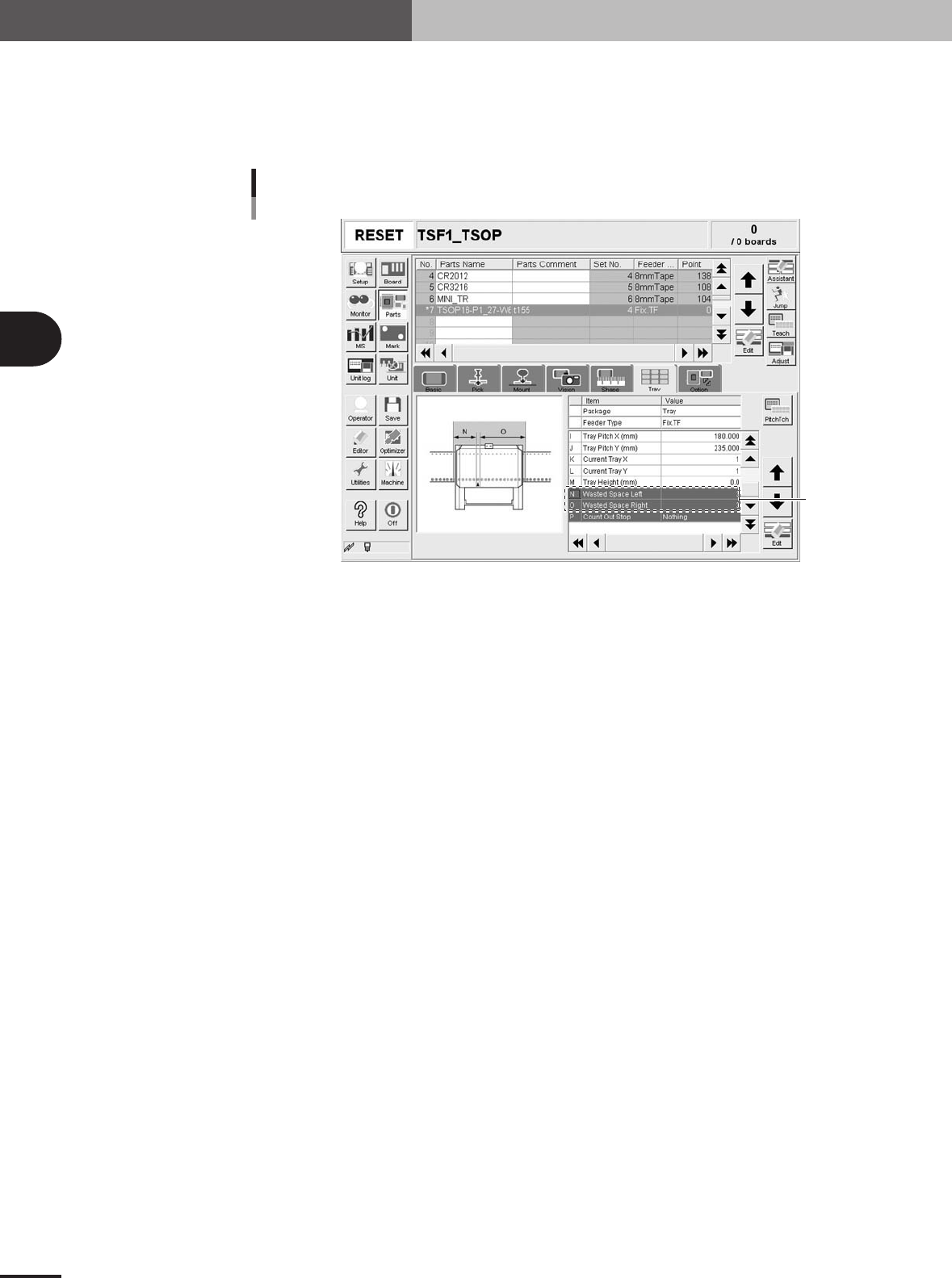
N, O: WastedSpace Left, Light
When a TSF1 is installed on the feeder plate, these parameters define the feeder set positions
where 8mm tape feeders cannot be attached to the feeder plate. These parameters should be set
with the Feeder No. specified in Step 5 as the reference. In the case of the TSF1, enter "3" in the
"WastedSpace Right" and WastedSpace Left" parameter fields.
WastedSpace Left, Light
TSF1
Set these
parameters.
27319-5E-20
P: CountOutStop
When this parameter is set to "Exist", the machine automatically stops when the specified number
of components is used up. When set to "Nothing", the machine returns to the first position to
continue component pickup after the specified number of components is used up. Normally set this
parameter to "Nothing".